
Contact module housing and contact module and fiber optic connector

A contact and connector technology, applied in the direction of coupling of optical waveguides, can solve the problems of increasing the plug insertion speed, increasing the difficulty of plug and socket insertion, and damage to the optical path, and achieves the effect of on-site disassembly and assembly

Inactive Publication Date: 2017-08-04
CHINA AVIATION OPTICAL-ELECTRICAL TECH CO LTD
View PDF1 Cites 2 Cited by
  • Summary
  • Abstract
  • Description
  • Claims
  • Application Information

AI Technical Summary

Problems solved by technology

The existing problem of this kind of optical connector is that the plug contacts and socket contacts do not have the function of on-site removal, and when multiple contacts are used at the same time, when part of the optical path is damaged, they cannot be quickly replaced.
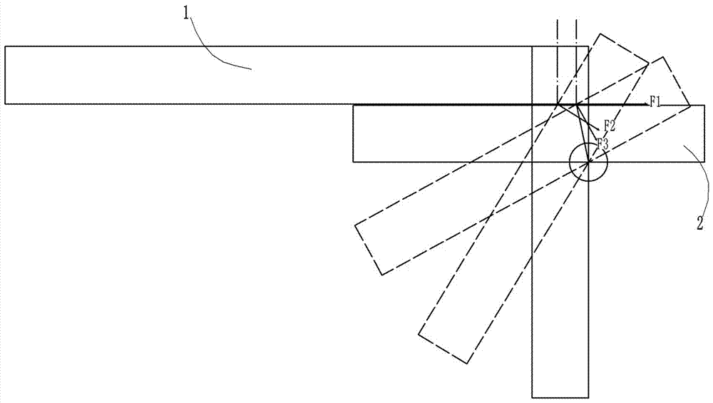
The existing problems of this dust-proof structure are: (1) the process of cooperation between the push plate and the dust-proof plate is as follows: figure 1 Shown: During the pushing process of push plate 1 and dust-proof plate 2, F1, F2, and F3 respectively represent the thrust direction of the push plate on the dust-proof plate during the rotation process of the dust-proof plate. During the rotation of the plate, the length of the force arm of the thrust of the push plate to the dustproof plate is always changing. When the push plate is in a vertical state, the force arm is the largest. That is to say, in order to realize the rotation of the dustproof plate, the required thrust is getting larger and larger. On the one hand, it will increase the difficulty of inserting the plug and socket; In order to realize the rotation of the dustproof plate, this large thrust will increase the insertion speed of the plug, and the plug and socket will have a greater impact to complete the insertion process of the plug and socket, which will reduce the service life of the plug. In addition, on the dustproof plate After being turned up completely, the dustproof plate cannot be hidden in the push plate, which will increase the size of the plug, which is not conducive to the miniaturization of the plug; (2) Even with the protection of the dustproof plate, it is still impossible to ensure that the optical fiber ferrule is in absolute position. In a dust-free environment, once the end face of the fiber optic ferrule is covered with dust, and the radius of the optical path formed by the fiber optic ferrule is relatively small, the optical density per unit area is relatively large, and the optical signal is highly sensitive to dust and dirt. Transmission is greatly disadvantaged

Method used


Image

  • Contact module housing and contact module and fiber optic connector
  • Contact module housing and contact module and fiber optic connector
  • Contact module housing and contact module and fiber optic connector

Examples


Embodiment Construction

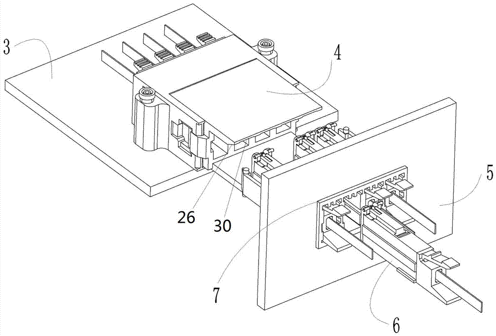
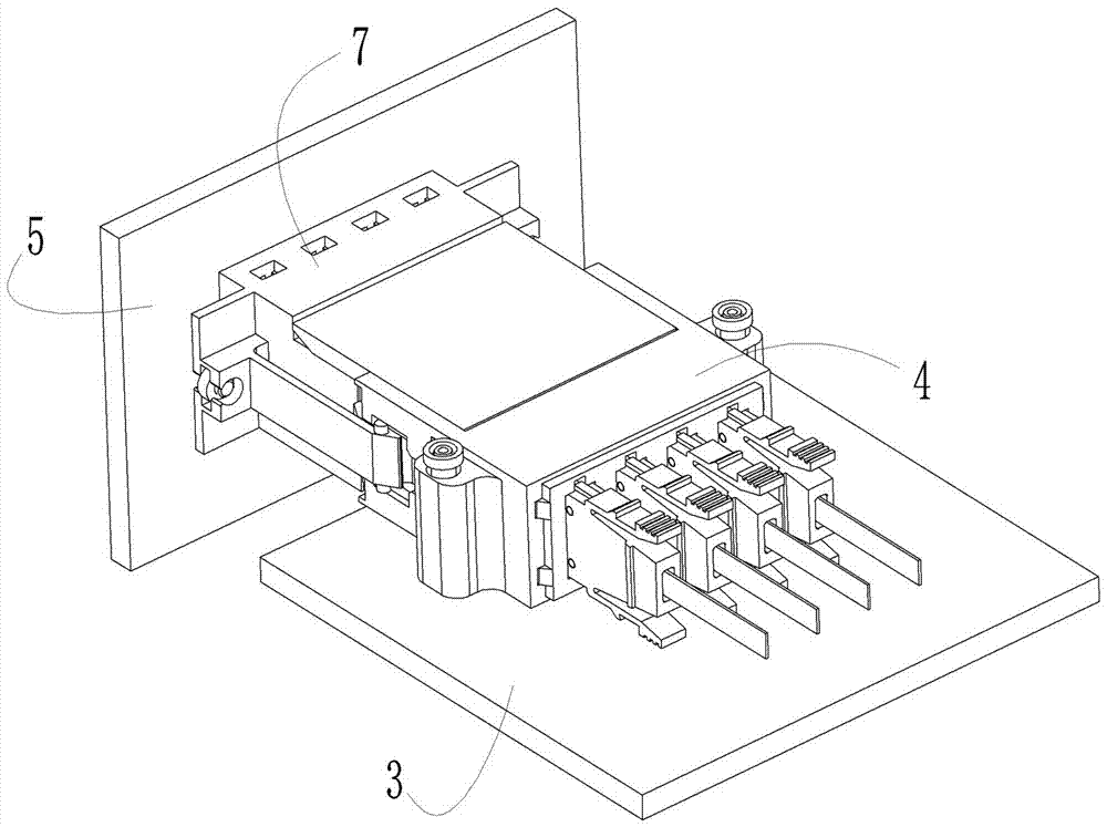
[0036] Examples of fiber optic connectors are Figure 2~12 As shown: the optical fiber connector in the present invention is an optical fiber receptacle 7 , which needs to be mated with an adapted optical fiber connector, that is, an optical fiber plug 4 in actual use. During use, the optical fiber socket is installed on the backboard 5 of the cabinet, and the optical fiber plug is installed on the sub-board 3 of the cabinet. The fiber optic socket is a combined socket with at least two socket contact modules 6, and the fiber optic plug is a combined plug with at least two plug contact modules. The optical fiber socket includes a socket connector frame 7 and four socket contact modules 6. The socket connector frame is used for installing the socket contact module and fixing it to the backplane. Module mounting hole 21, the shape of the module mounting hole is a rectangle, the left and right sides of the module mounting hole are provided with guide keyways 23 extending along t...


PUM


Abstract

The invention relates to a contact module shell, a contact module and an optical fiber connector. The contact module shell includes a shell body for being inserted into a module mounting hole of a corresponding connector frame from the back to the front, and the shell body is provided with a limit The housing stop surface facing forward is used to block and cooperate with the module stop structure on the connector frame to limit the forward movement limit of the housing body. The housing body is provided with a contact installation for the corresponding optical fiber contact installation The housing body is also provided with a module locking hook for elastically snapping into the module slot on the hole wall of the module installation hole to limit the housing body to move backward. The invention provides a contact module shell that can be disassembled from a connector frame on site, and a contact module and an optical fiber connector using the contact module shell.

Description

technical field [0001] The invention relates to a contact module, an optical fiber connector and an optical fiber connector assembly in the field of signal transmission. Background technique [0002] In the cabinet of communication equipment, data communication needs to be carried out between the backplane and the sub-board. At present, the relatively mature communication method is to use high-speed differential electrical connector transmission. Due to the defects of electrical signal transmission, this communication method has certain advantages. transmission limit. [0003] However, if the data communication between the backplane and the sub-board is transmitted by optical fiber, the transmission capacity will be much higher than that of the existing electrical transmission. Existing optical fiber connectors used between the mechanism backplane and sub-boards, such as the "optical connector for backplane" disclosed in Chinese patent CN104412141A, the optical connectors d...

Claims


Application Information

Patent Timeline
Patent Type & Authority Patents(China)
IPC IPC(8): G02B6/38
Inventor 覃道振刘卫锋刘涛
Owner CHINA AVIATION OPTICAL-ELECTRICAL TECH CO LTD
Learn More