Lock unit having a multi-pawl locking mechanism

A technology of locking unit and reset element, which is applied in the application of locks, building locks, vehicle locks, etc.

Inactive Publication Date: 2011-08-24
KIEKERT AG
View PDF5 Cites 7 Cited by
  • Summary
  • Abstract
  • Description
  • Claims
  • Application Information

AI Technical Summary

Problems solved by technology

The locking mechanism proved to be efficient, but still needs further improvement

Method used


Image

  • Lock unit having a multi-pawl locking mechanism
  • Lock unit having a multi-pawl locking mechanism
  • Lock unit having a multi-pawl locking mechanism

Examples


Embodiment Construction

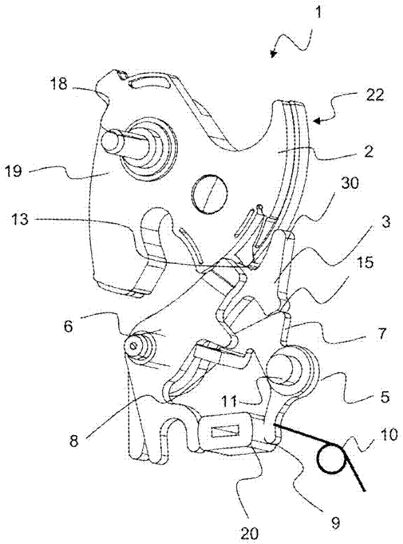
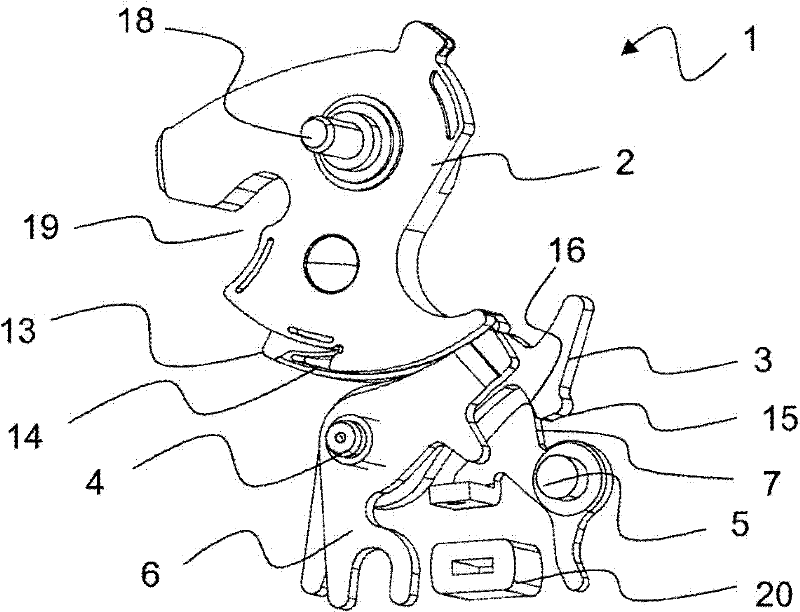
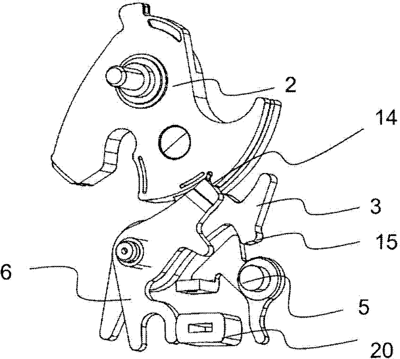
[0025] figure 1 A perspective view showing the multi-part locking mechanism of the locking unit 1 of the present invention. The key component of the locking unit 1 is the catch 2 , which is rotatably (spring-type) mounted near the catch shaft 18 . The inlet opening 19 for the clip pin is shown on the left side of the figure. The clip 2 includes at its bottom a main position 13 next to the inlet opening 19, and a first position 14, in different adjacent planes perpendicular to the clip axis of rotation 18.

[0026] When the locking unit 1 is in the open position, the first pawl 3 and the second pawl 6 are provided near the circumference of the catch 2 . In the figure, the first pawl 3 and the second pawl 6 are rotatably provided on the common pawl shaft 4 and are stamped components. The first pawl 3 and the second pawl 6 are in different planes, and this arrangement corresponds to the fact that the main position 13 and the first position 14 of the catch 2 are in different pl...


PUM


Abstract

The invention relates to a lock unit (1), comprising at least one rotary latch (2), a first pawl (3) having a pawl rotational axis (4), and a blocking lever (5), wherein the rotary latch (2) introduces a pivot moment into the first pawl (3) in the locked state of the lock unit (1) and the first pawl (3) is fixed by way of the blocking lever (5), wherein a second pawl (6) is provided, which is mounted on the pawl rotational axis (4) and can be engaged in the blocking lever (5) and the rotary latch (2) and the first pawl (3) has a curved first blocking region (12) for a main detent (13) of the rotary latch (2).

Description

Field of Invention [0001] The present invention relates to a locking unit for an automobile, and more particularly, the present invention relates to a locking unit having a multi-part locking mechanism. Background technique [0002] In the locking unit, the relative position between the catch and the catch is usually neither the force exerted by the catch is transmitted through the catch shaft, nor is the catch alone fixed by the catch. Conversely, for quiet operation of the locking unit, the force exerted by the catches transmits the moment directly to the catches, which facilitates the release of the catches. In this way, the catch (individually) transmits the opening torque to the first catch and can easily be moved to the open position due to the spring preload of the catch and / or the force transmitted to the catch (indirectly) from the door weather strip . [0003] In order to ensure a secure locking, a stop lever is provided which holds the first pawl in the locked p...

Claims


Application Information

Patent Timeline
Patent Type & Authority Applications(China)
IPC IPC(8): E05B65/32
CPCE05B85/26Y10T292/108
Inventor 迈克尔·史古茨马莱克·佐兰根
Owner KIEKERT AG
Why Eureka
Try Eureka