Ultrasonic auxiliary micro injection forming die

A molding mold and ultrasonic technology, applied in the field of polymer ultrasonic-assisted micro-injection molding molds, can solve problems such as uneven heat loss, narrow processing temperature range, high material melting temperature and mold temperature, and improve fluidity and filling performance, improved injection molding quality, viscosity and elastic reduction effects

Active Publication Date: 2013-03-13
TIANJIN UNIV
View PDF4 Cites 0 Cited by
  • Summary
  • Abstract
  • Description
  • Claims
  • Application Information

AI Technical Summary

Problems solved by technology

As polymer MEMS and MST require smaller and smaller micro-featured structures of polymer devices, the existing micro-injection molding technology has the following problems: (1) due to the unevenness of heat loss and Uncertainty causes the shape accuracy of micro-devices to fail to meet higher-level requirements stably; (2) For polymers with high viscosity, it is not easy to fill the mold cavity during injection molding of microstructures with high aspect ratios; (3) ) Compared with conventional injection molding, micro-injection molding requires higher material melting temperature and mold temperature, which brings difficulties to the design and manufacture of micro-injection molding systems; (4) The design and manufacture of micro-mold cores cannot Meet the needs of the development of microstructure production; (5) For polymers that are easy to decompose, the processing temperature range is very narrow, and the processing conditions are difficult to control; (6) The high aspect ratio microstructure is easily damaged, and the polymer adheres to the micromold Larger, there is currently no effective means of demoulding

Method used


Image

  • Ultrasonic auxiliary micro injection forming die
  • Ultrasonic auxiliary micro injection forming die
  • Ultrasonic auxiliary micro injection forming die

Examples


Embodiment Construction

[0013] Below in conjunction with specific embodiment, and with reference to accompanying drawing, technology of the present invention is described further:

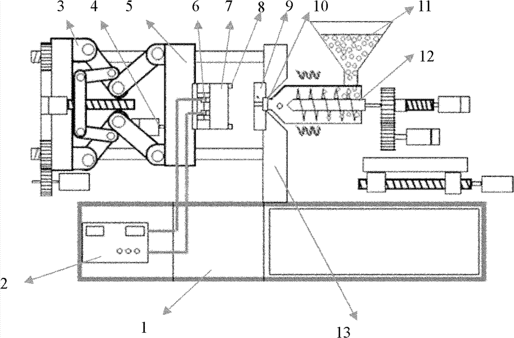
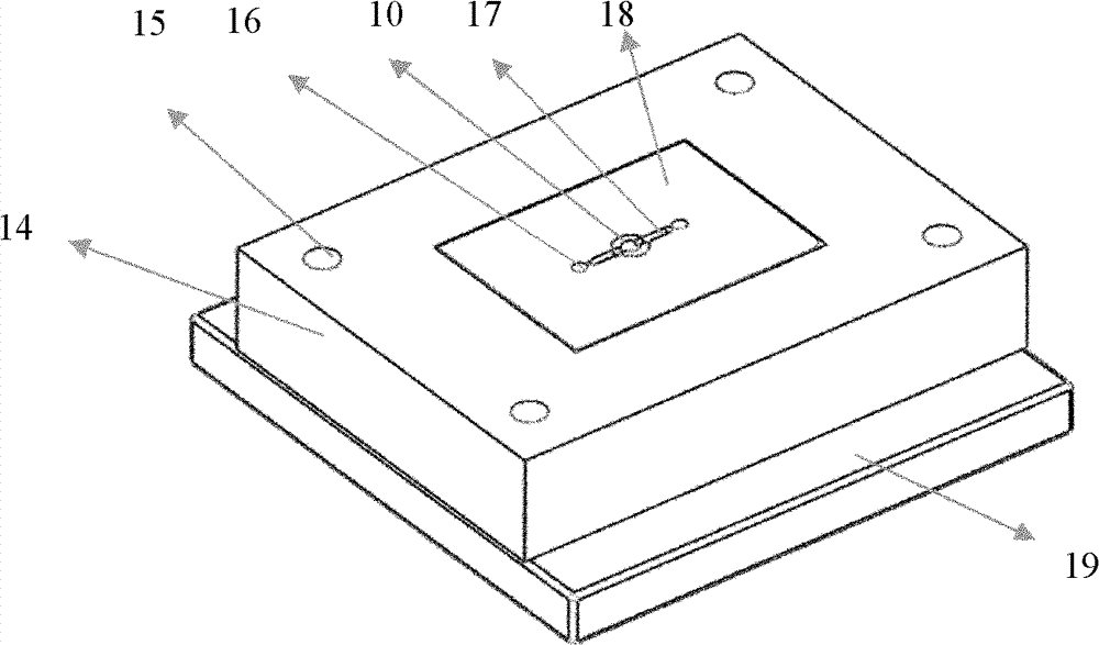
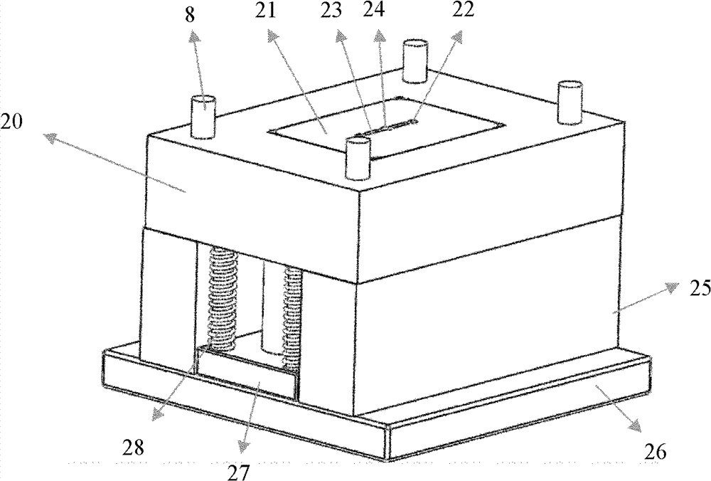
[0014] A kind of ultrasonic-assisted micro-injection molding mold as shown in the figure, it comprises static mold 9 and moving mold 7, described static mold 9 comprises static mold fixed plate 19, is connected with static mold on described static mold fixed plate 19 The template 14 is fixedly connected with the static mold insert 18 on which the static mold core 16, the sprue bushing 10 and the static mold runner 17 are fixedly connected in the middle of the static mold template 14; the movable mold 7 Including the movable mold template 20 fixedly connected with the movable mold insert 21 in the middle, the movable mold fixed plate 26 is fixedly connected with the movable mold template 20 arranged above it through the baffle plate 25 (can be a square iron), and the baffle plate 25 is connected with the movable mold templa...


PUM


Abstract

The present invention discloses an ultrasonic auxiliary micro injection forming die. The die comprises a fixed die and a moving die, wherein the fixed die comprises a fixed die fixed plate, and a fixed die template is connected with the fixed die fixed plate. The moving die comprises a moving die template which is connected with a moving die insert in the middle, a moving die fixed plate is fixedly connected with the moving die template arranged above through a baffle plate. A push plate supporting device is arranged in the middle of the moving die fixed plate, and a support is fixedly arranged between the push plate and the moving die template through a pillar support. A spring is arranged between the push plate and the moving die template, and an energy transducer is connected with an ultrasonic generator. Every set of piezoelectric ceramics is connected, in a manner of being compressed, with the bottom surface of the support through double ended screws, the top end of every double ended screw is in threaded connection with the lower part of a horn, and the top part of every horn is connected with a moving die core. By adopting the device, not only the fluidity and filling performance of polymer melt can be improved, but the physical property of micro injection molded parts can also be enhanced.

Description

technical field [0001] The invention relates to injection molding and micro-injection molding processing of polymer material devices, in particular to polymer ultrasonic-assisted micro-injection molding molds. Background technique [0002] With the wide application of polymer materials in the manufacture of microstructures, the manufacturing technology of polymer microstructures has become a key issue in the manufacture of polymer microelectromechanical systems (MEMS) and microsystems (MST). At present, micro-injection molding technology is considered to be the most important manufacturing method for polymer microstructure, which has the characteristics of simple manufacturing process, low manufacturing cost, and easy mass production. [0003] However, the current micro-injection molding technology is still mostly in accordance with the traditional conventional injection molding technology mode, to increase the shear stress of the polymer melt by increasing the injection spe...

Claims


Application Information

Patent Timeline
Patent Type & Authority Patents(China)
IPC IPC(8): B29C45/26
CPCB29C2045/0094B29C45/5675B29C2791/008
Inventor 仇中军郑辉赵怀学房丰洲
Owner TIANJIN UNIV
Why Eureka
Try Eureka