
Vehicle body front part structure

一种车身前部、腿部的技术,应用在上部结构、上部结构分总成、车辆部件等方向,能够解决铁锈、裙板侧构件易变形等问题,达到提高减震性能、材料质量和板厚度最优化、提高能量吸收效率的效果

Inactive Publication Date: 2011-08-31
SUZUKI MOTOR CORP
View PDF6 Cites 7 Cited by
  • Summary
  • Abstract
  • Description
  • Claims
  • Application Information

AI Technical Summary

Problems solved by technology

However, according to the conventional structure described above, the sealing material cannot be applied to the joint portion of the tray bracket located outside in the vehicle width direction (the joint portion between the pair of front side walls and the rear side wall 30S), so that water intrudes into the joint portion of the joint portion. between surfaces and sometimes forms rust
[0006] Moreover, in the above vehicle body front structure, the apron side member is easily deformed in the event of a vehicle frontal collision.

Method used


Image

  • Vehicle body front part structure
  • Vehicle body front part structure
  • Vehicle body front part structure

Examples


Embodiment Construction

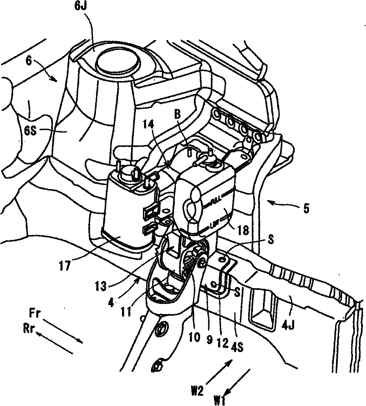
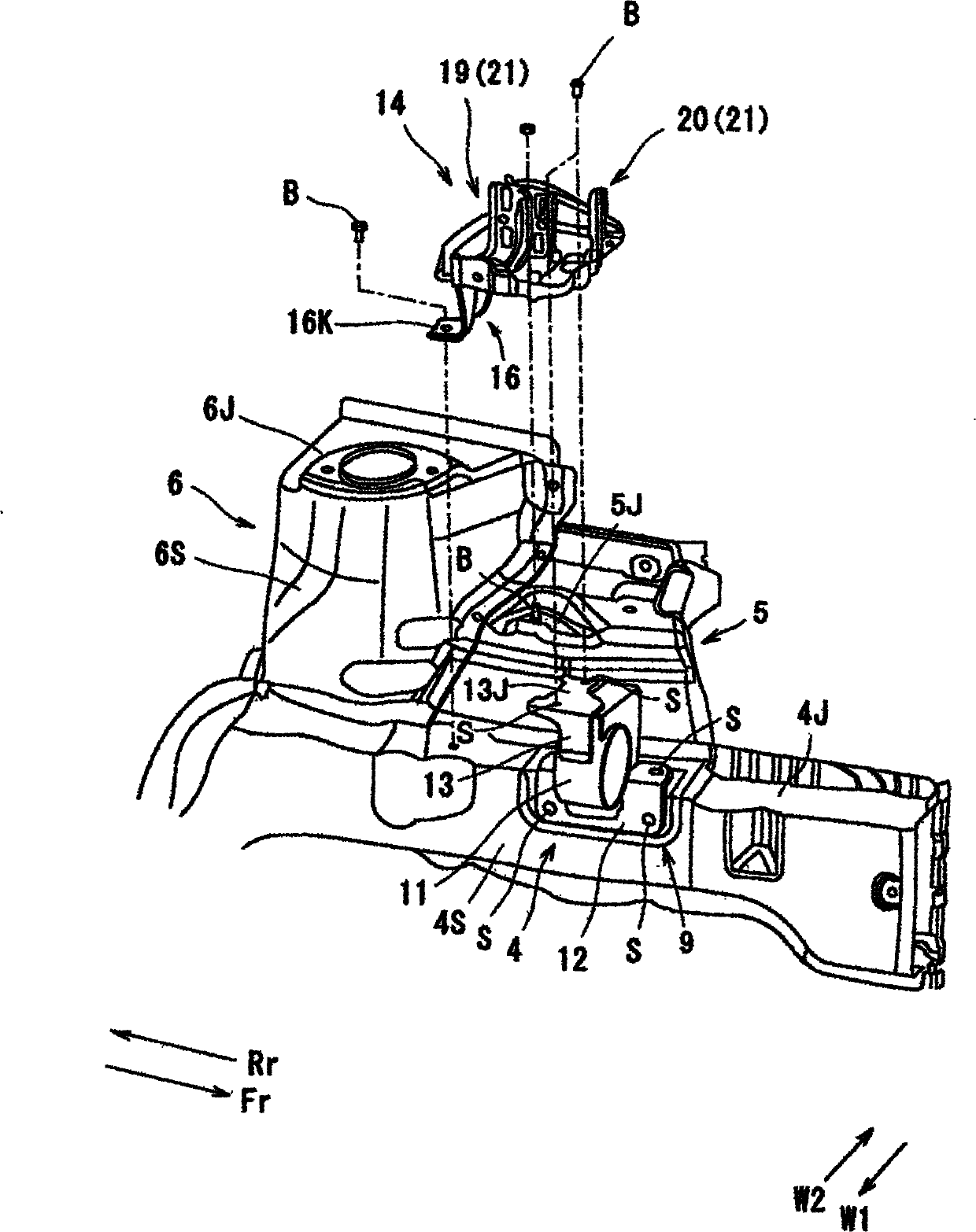
[0031] figure 1 And FIG. 3(a) and FIG. 3(b) show the front structure of the vehicle body of the motor vehicle. The structure of the front part of the vehicle body includes: a dash panel 3 separating the cabin 2 from the engine room 1; a rectangular tubular skirt side member 4 extending in the longitudinal direction of the vehicle; a skirt side plate 5; The interior W1 in the vehicle width direction extends to the strut tower portion 6 in the engine compartment 1 .

[0032] The strut tower portion 6 includes: an outer peripheral wall 6S having a trapezoidal cross-section narrowed toward the inside W1 in the vehicle width direction; and an upper wall 6J connected to the upper end portion of the outer peripheral wall 6S and combined with Suspension for front wheels. The corners in the cross section of the outer peripheral wall 6S are curved in an arc shape. The apron side panel 5 is joined to the apron side member 4 by welding, and a part of the apron side panel 5 protrudes t...


PUM


Abstract

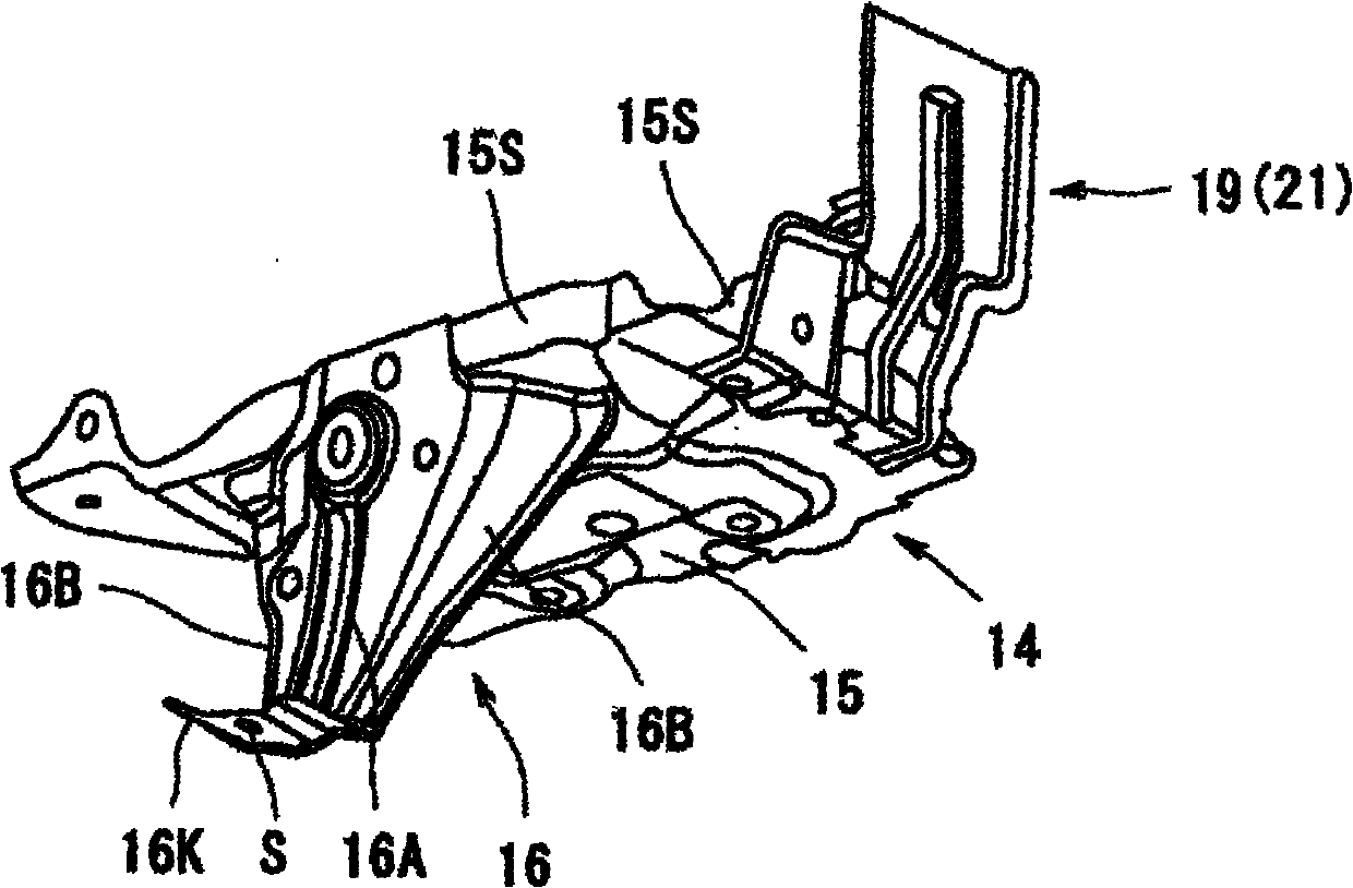
A vehicle body front part structure has an apron side panel 5 joined to an apron side member 4 extending along the vehicle longitudinal direction, and a tray 14 for battery supported on the apron side member 4. In the front part structure, a leg part 16 is provided in an tray body part 15, a lower end part 16K of the leg part 16 is fixed to the apron side member 4 with a fixing member B, and the leg part 16 is formed of a plate material so that the deformation of the apron side member 4 is allowed when a vehicle longitudinal force is applied to the apron side member 4.

Description

technical field [0001] The present invention relates to a vehicle body front structure in which a apron side panel is connected to a apron side member extending in the vehicle longitudinal direction, and a battery tray is supported at the apron side member. Background technique [0002] Traditionally, in body front structures such as Figure 9 As shown, a pair of front and rear tray brackets 30 are welded to the apron side member 4 on the vehicle front side Fr of the strut tower 6 , and the tray 14 is placed on the tray bracket 30 and fixed by bolts B on the tray support 30 . [0003] As viewed from the side (as viewed in the vehicle width direction), the tray bracket 30 forms a U-shaped cross section whose lower side is open, and each of the pair of front and rear side walls 30S of the tray bracket 30 A lower end portion having an L-shaped cross section is welded and fixed to the upper wall 4J of the apron side member 4 and the side wall 4S of the interior W1 of the apron ...

Claims


Application Information

Patent Timeline
Patent Type & Authority Applications(China)
IPC IPC(8): B62D25/08B60R16/04B60K5/12
CPCB60R16/04B60R16/0238
Inventor 曾我部道弘
Owner SUZUKI MOTOR CORP
Learn More