
Heat pump system and control method thereof

A technology of a heat pump system and a control method, which is applied to heat pumps, refrigerators, refrigeration components, etc., can solve problems such as the inability to control the temperature of the water tank.

Inactive Publication Date: 2011-08-31
SAMSUNG ELECTRONICS CO LTD
View PDF4 Cites 10 Cited by
  • Summary
  • Abstract
  • Description
  • Claims
  • Application Information

AI Technical Summary

Problems solved by technology

[0004] If a consumer who already uses a tank without a temperature sensor buys only an outdoor unit and an indoor unit, it may not be possible to control the temperature of the tank

Method used


Image

  • Heat pump system and control method thereof
  • Heat pump system and control method thereof
  • Heat pump system and control method thereof

Examples


Embodiment Construction

[0027] Embodiments will now be described in detail, examples of which are illustrated in the accompanying drawings, wherein like reference numerals refer to like elements throughout.

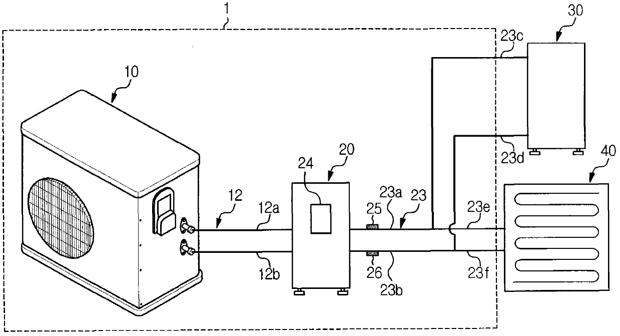
[0028] figure 1 is a schematic diagram showing the overall configuration of a heat pump system according to one embodiment.

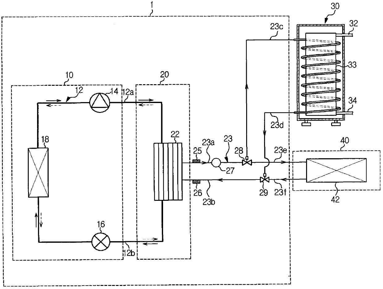
[0029] The heat pump system 1 according to this embodiment includes: an outdoor unit 10; an indoor unit 20; a refrigerant circulation pipe unit 12 connected between the outdoor unit 10 and the indoor unit 20; a water circulation pipe unit 23 connected to the indoor unit 20 and the load 30 Between and 40; the first temperature sensor 25 and the second temperature sensor 26 are installed in the position of the water circulation pipe unit 23 close to the indoor unit 20. As an example of load, figure 1 Shown is a hot water tank 30 for supplying hot water and a heating load 40 such as an interior floor.

[0030] The refrigerant circulation pipe unit 12 includes: a first ref...


PUM


Abstract

The invention provides a heat pump system and control method thereof. The heat pump system, the operation of which is controlled using a temperature difference between a water inlet and a water outlet of a heat exchanger, exchanging heat between a refrigerant and water, and a control method thereof. The heat pump system includes temperature sensors installed on a water circulation pipe unit at water inlet and outlet sides of a heat exchanger, and heats a load to a set temperature by controlling a compressor or an expander according to a difference between temperatures sensed by the temperature sensors. Here, a temperature of water transmitted to the load is set to be greater than a target load temperature by a reference value, and if the temperature difference is smaller than a designated value, the operation of the heat pump system is stopped.

Description

technical field [0001] Embodiments relate to a heat pump system that supplies heat to a heating load or a hot water load using a heat pump and a control method thereof. Background technique [0002] Generally, a heat pump system includes a compressor, an outdoor air exchanger, an expander, a water-refrigerant heat exchanger, and an indoor heat exchanger to heat an indoor floor or cool and heat indoor air using the heat of the heat pump. [0003] Specifically, the heat pump system may cool and heat an indoor space or heat water in a water tank using a water pipe through which cold or hot water passes. Here, the temperature of the water tank is controlled using a temperature sensor installed on the water tank, thereby heating the water in the water tank to supply hot water. [0004] If a consumer who has already used a water tank without a temperature sensor buys only an outdoor unit and an indoor unit, it may not be possible to control the temperature of the water tank. The...

Claims


Application Information

Patent Timeline
Patent Type & Authority Applications(China)
IPC IPC(8): F25B30/02F25B49/02
CPCY02B30/741F25B2600/0253F25B2600/2513F24H4/04F24H9/2021F25B2339/047F25B30/02F25B2700/21161Y02B30/70F24H15/385F24H15/38F24H15/281F24H15/32F24H15/37F24H15/219F24H15/174F24H15/215
Inventor 金成九吴宰爀郑东云朴昌绪
Owner SAMSUNG ELECTRONICS CO LTD
Learn More