Vacuum pump

A vacuum pump and rotor technology, applied to pumps, pump components, axial flow pumps, etc., can solve the problems of increasing the risk of collision, changing other properties of pump rotors, accelerating material fatigue, etc., to achieve the effect of ensuring originality and licensing qualification

Inactive Publication Date: 2011-04-06
OERLIKON LEYBOLD VACUUM
View PDF2 Cites 5 Cited by
  • Summary
  • Abstract
  • Description
  • Claims
  • Application Information

AI Technical Summary

Problems solved by technology

Increased risk of collision due to excessive rotor temperature, accelerated material fatigue and changes in other properties of the pump rotor

Method used


Image

  • Vacuum pump
  • Vacuum pump

Examples


Embodiment Construction

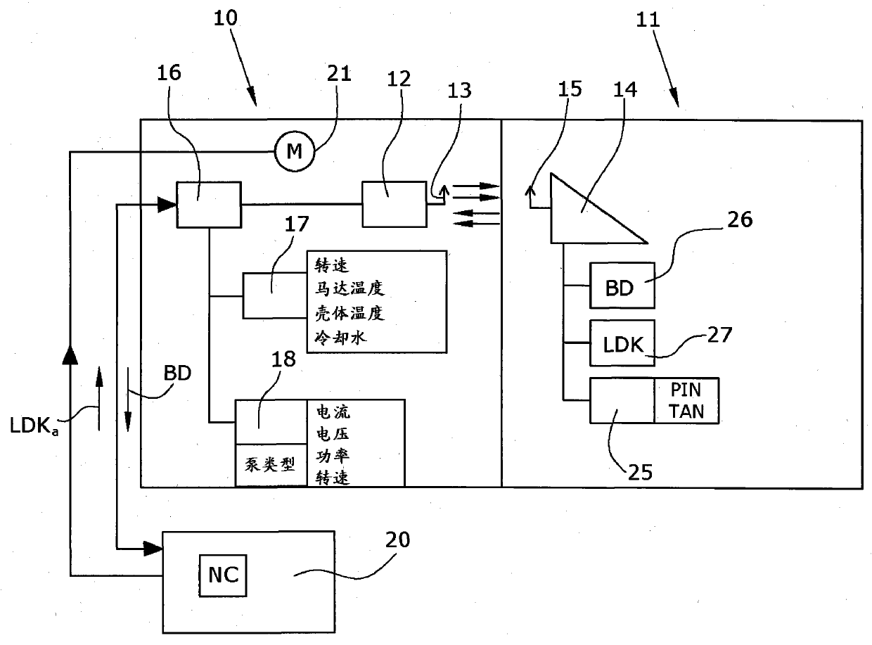
[0016] The construction of the vacuum pump is the same as in WO 2007 / 025854 A1, the content of which is incorporated into this description by reference. The vacuum pump is a turbomolecular pump with a rapidly rotating pump rotor. Interengaging vane rows are located on the pump rotor and the pump stator. Only the pump stator 10 and the pump rotor 11 are shown schematically in the figures, since in this context it is primarily the communication system that is relevant to the invention.

[0017] The pump stator contains a reader 12 of a radio frequency identification (RFID) system. The reader is connected to the stator antenna 13 . The pump rotor contains an RFID transponder 14 or tag with a rotor antenna 15 . Data transmission between reader 12 and transponder 14 takes place wirelessly and bidirectionally via antennas 13 and 15 .

[0018] The reader 12 is provided with a (not shown) power supply. The transponder 14 can be powered wirelessly by the reader via the antennas 13...


PUM


Abstract

The invention relates to a vacuum pump with a pump stator (10) and a pump rotor (11). The pump rotor (11) contains a transponder (14) that can be read out by a reader of the pump stator. The pump rotor (11) also contains sensors (26) for determining operating data (BD), and a memory (27). The memory (27) stores either the history of the measured operating data (BD) or a service life characteristic (LDK). In this way, the rate of wear of the respective rotor is determined and stored in the rotor, and the rotor therefore contains all of the information relating to maintenance. The rotor-related information remains in the rotor even if the rotor is used in another vacuum pump.

Description

technical field [0001] The invention relates to a vacuum pump with a pump rotor and a pump stator, wherein the pump rotor has a transponder with a rotor antenna, and the pump stator has a reader with a stator antenna and at least one device for detecting wear-related operating data sensor. Background technique [0002] In WO 2007 / 025854 A1 (Leybold Vacuum GmbH) a vacuum pump is described in which the pump rotor carries electronic sensors such as temperature sensors. A transmitting antenna is arranged on the pump rotor, which transmits the data of the sensors to a receiving antenna of the stator. It is thus possible to transmit precise measured values ​​from the pump rotor to the pump stator. [0003] Vacuum pumps, especially turbomolecular pumps that rotate rapidly at speeds between 10,000 rpm and more than 100,000 rpm, are highly sophisticated devices whose components are subjected to extreme loading due to compression heat, frictional heat, and centrifugal forces. Due t...

Claims


Application Information

Patent Timeline
Patent Type & Authority Applications(China)
IPC IPC(8): F04D19/04F04D27/00F04D29/32G08C17/00
CPCH04Q9/00F04D29/32F04D27/001F04D19/042H04Q2209/47
Inventor 阿洛伊斯·格雷文克里斯蒂安·拜尔
Owner OERLIKON LEYBOLD VACUUM
Why Eureka
Try Eureka