Current measurement device

A current measuring device and current technology, applied in the direction of measuring devices, measuring electrical variables, voltage/current isolation, etc., can solve the problems of not being able to support super large current measurement, measurement accuracy, poor temperature characteristics, and low linear measurement range, etc. Achieve the effects of wide linear measurement range, good temperature characteristics and low power consumption

Active Publication Date: 2013-01-30
MULTIDIMENSION TECH CO LTD
View PDF6 Cites 0 Cited by
  • Summary
  • Abstract
  • Description
  • Claims
  • Application Information

AI Technical Summary

Problems solved by technology

Among them, due to the low sensitivity of the Hall sensor, ferromagnetic materials are often used to improve the sensitivity and accuracy through the magnetic effect; the current sensor using magneto-optical glass and all-fiber as the sensor unit has the advantage of a wide range, but its measurement accuracy, Poor temperature characteristics and high power consumption; while the linear measurement range of a single TMR sensor is lower than that of the Hall sensor, it cannot support the measurement of large currents

Method used


Image

  • Current measurement device
  • Current measurement device
  • Current measurement device

Examples


Embodiment 1

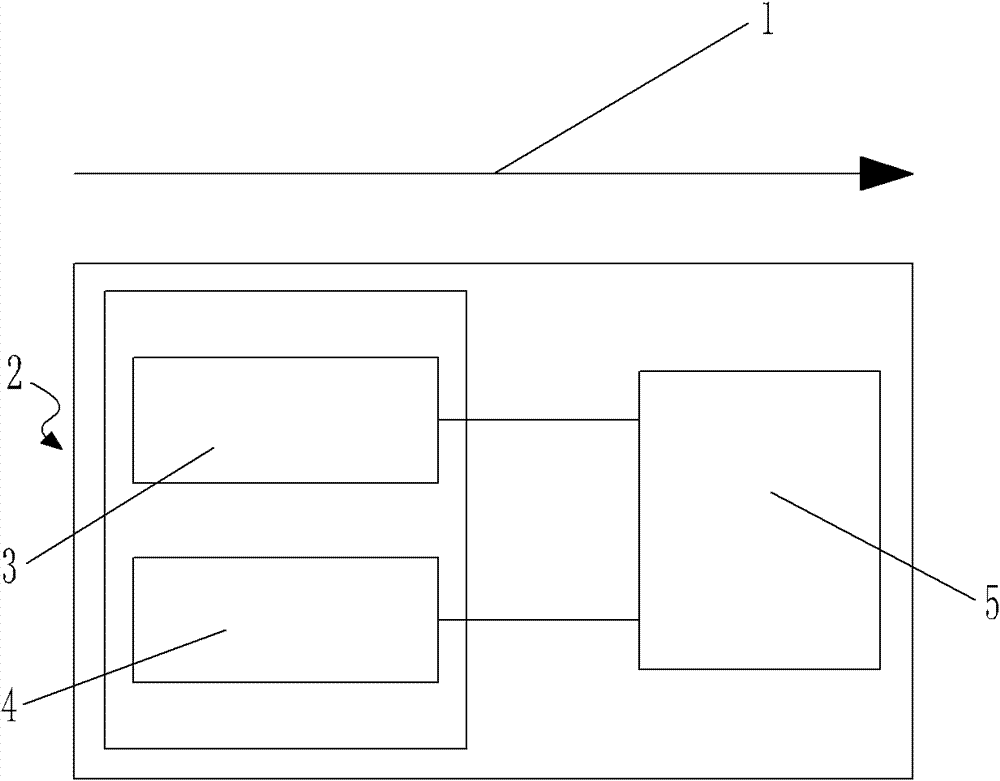
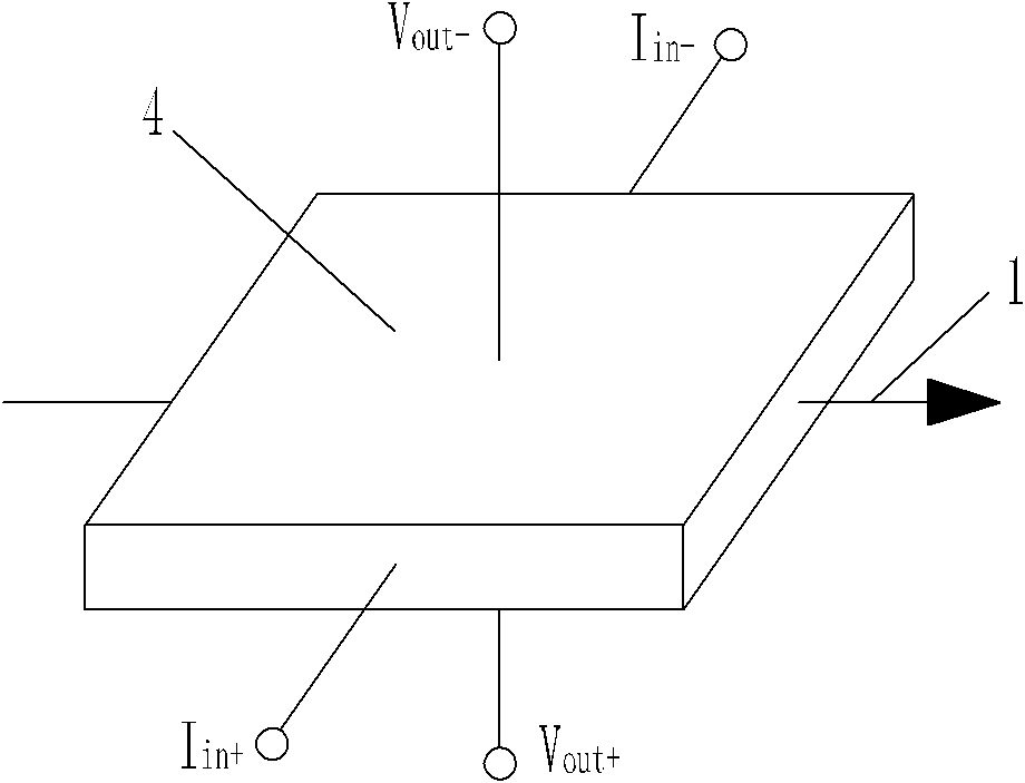
[0021] Embodiment one: as attached figure 1 As shown, the current measuring device includes a measuring unit 2, and the measuring unit 2 includes a first sensor 3 arranged parallel to the tangential direction of the magnetic field generated around the conducting wire and a second sensor arranged parallel to the first sensor 3 4. The first sensor 3 is a TMR sensor, and the second sensor 4 is a Hall sensor. The dedicated ASIC chip 5 is packaged together, and the electromagnetic principle of the Hall sensor is as attached figure 2 As shown, where Iin+ and Iin- are the current input terminals, which are input from opposite ends of the diaphragm, and Vout+ and Vout- are the output voltage terminals, which are respectively drawn out from the direction perpendicular to the surface of the diaphragm, so that the magnetic field around the current-carrying wire The direction of 1 is perpendicular to the direction of the input circuit and the output voltage. According to the working...

Embodiment 2

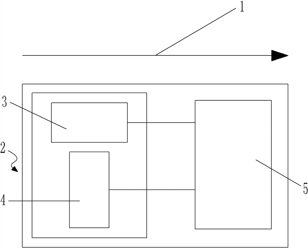
[0022] Embodiment two: as attached image 3 As shown, the current measuring device includes a measuring unit 2, and the measuring unit 2 includes a first sensor 3 parallel to the tangential direction of the magnetic field 1 around the conducting wire and a second sensor perpendicular to the first sensor 3. 4. The first sensor 3 is a TMR sensor, and the second sensor 4 is a Hall sensor, both of which are respectively connected to a sensor-specific ASIC chip 5 that matches both, and the first sensor 3 and the second sensor 4 and the sensor-specific ASIC chip 5 are packaged together, and the electromagnetic principle of the Hall sensor is as attached Figure 4 As shown, where Iin+ and Iin- are the current input terminals, which are input from the opposite ends of the diaphragm, Vout+ and Vout- are the output voltage terminals, and are respectively drawn from the other pair of opposite ends of the diaphragm, so that the current-carrying wire The direction of the surrounding ma...

Embodiment 3

[0023] Embodiment three: as attached Figure 5 As shown, the current measuring device includes a measuring unit 2, and the measuring unit 2 includes a first sensor 3 parallel to the tangential direction of the magnetic field 1 around the conducting wire and a second sensor 3 arranged at an angle θ with the first sensor 3. Sensor 4, wherein, 0° Figure 6 As shown, define the component of the magnetic field 1 around the current-carrying wire in the direction perpendicular to the second sensor 4 as H', then the H' measured by the second sensor 4=H×cos(π-θ), so H' is less than H, so use the TMR sensor with a lower range to measure a component of the magnetic field 1 around the current conducting wire, and then calculate the size of the magnetic field 1 around the current conducting wire through the relevant formula, so as to realize the measurement of the current in the current conducting wire In this embodiment, the Hall sensor with a higher range is not needed, and the sensiti...


PUM


Abstract

The invention discloses a current measuring device, which is used to measure the current in the current-carrying wire, which includes several measuring units, and each measuring unit includes a device for measuring The first sensor for the current value in the low-range range, and the second sensor for measuring the current value in the high-range range are set at an angle to the tangential direction of the magnetic field around the live wire. The first sensor and the second sensor are located in the same and The conducting wires are located in a plane perpendicular to the straight line, and the two are respectively connected to the sensor-specific ASIC chip. The present invention utilizes the advantages of the high sensitivity of the TMR sensor and the wide linear measurement range of the Hall sensor, or utilizes the inclined TMR sensor to measure the component of the magnetic field around the energized wire, which not only has high sensitivity, but also has a wide linear measurement range, and at the same time It has the advantages of good temperature characteristics, high response frequency, low power consumption and small size.

Description

technical field [0001] The invention relates to a wide-range current measuring device made by using the tunnel junction magnetoresistance effect (TMR) as the high-sensitivity characteristic of the sensor and the high-range of the Hall sensor. Background technique [0002] Current measurement devices generally measure current through the magnetic field generated by the measured current. Currently, commonly used current measurement devices include Hall sensors, anisotropic magnetoresistance (AMR) sensors, giant magnetoresistance (GMR) sensors, Rogowski coils, magneto-optic glass sensors or full fiber optic sensors. Among them, due to the low sensitivity of the Hall sensor, ferromagnetic materials are often used to improve the sensitivity and accuracy through the magnetic effect; the current sensor using magneto-optical glass and all-fiber as the sensor unit has the advantage of a wide range, but its measurement accuracy, The temperature characteristics are poor, and the po...

Claims


Application Information

Patent Timeline
Patent Type & Authority Patents(China)
IPC IPC(8): G01R15/20G01R19/00
Inventor 詹姆斯·G·迪克雷啸锋黎伟王建国薛松生
Owner MULTIDIMENSION TECH CO LTD
Why Eureka
Try Eureka