Printed circuit board and differential wire wiring method

A technology of printed circuit boards and wiring methods, which is applied in the direction of printed circuits, printed circuits, printed circuit components, etc., can solve the problems of unequal lengths of non-parallel sections, incomplete synchronization of differential signal transmission, and inability to enter parallel sections at the same time, etc. Achieve accurate coupling, improve anti-interference ability, and improve the effect of synchronization

Inactive Publication Date: 2011-08-31
HONG FU JIN PRECISION IND (SHENZHEN) CO LTD +1
View PDF3 Cites 13 Cited by
  • Summary
  • Abstract
  • Description
  • Claims
  • Application Information

AI Technical Summary

Problems solved by technology

In the existing design, only the total lengths of the two differential lines are equal, but the problem of unequal lengths of non-parallel segments is ignored
This prevents the differential signal from entering the parallel segment through non-parallel segments of different lengths, and cannot enter the parallel segment at the same time, resulting in incomplete synchronization of the transmission of the differential signal after entering the parallel segment.
When the frequency of the differential signal is higher and higher, this incomplete synchronization will more and more obviously affect the anti-interference ability of the differential signal

Method used


Image

  • Printed circuit board and differential wire wiring method
  • Printed circuit board and differential wire wiring method
  • Printed circuit board and differential wire wiring method

Examples


Embodiment Construction

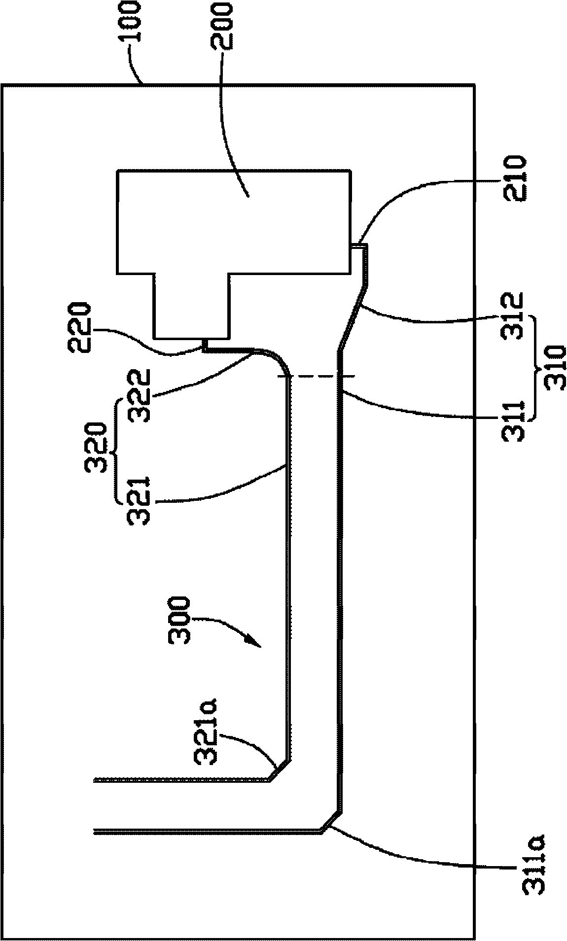
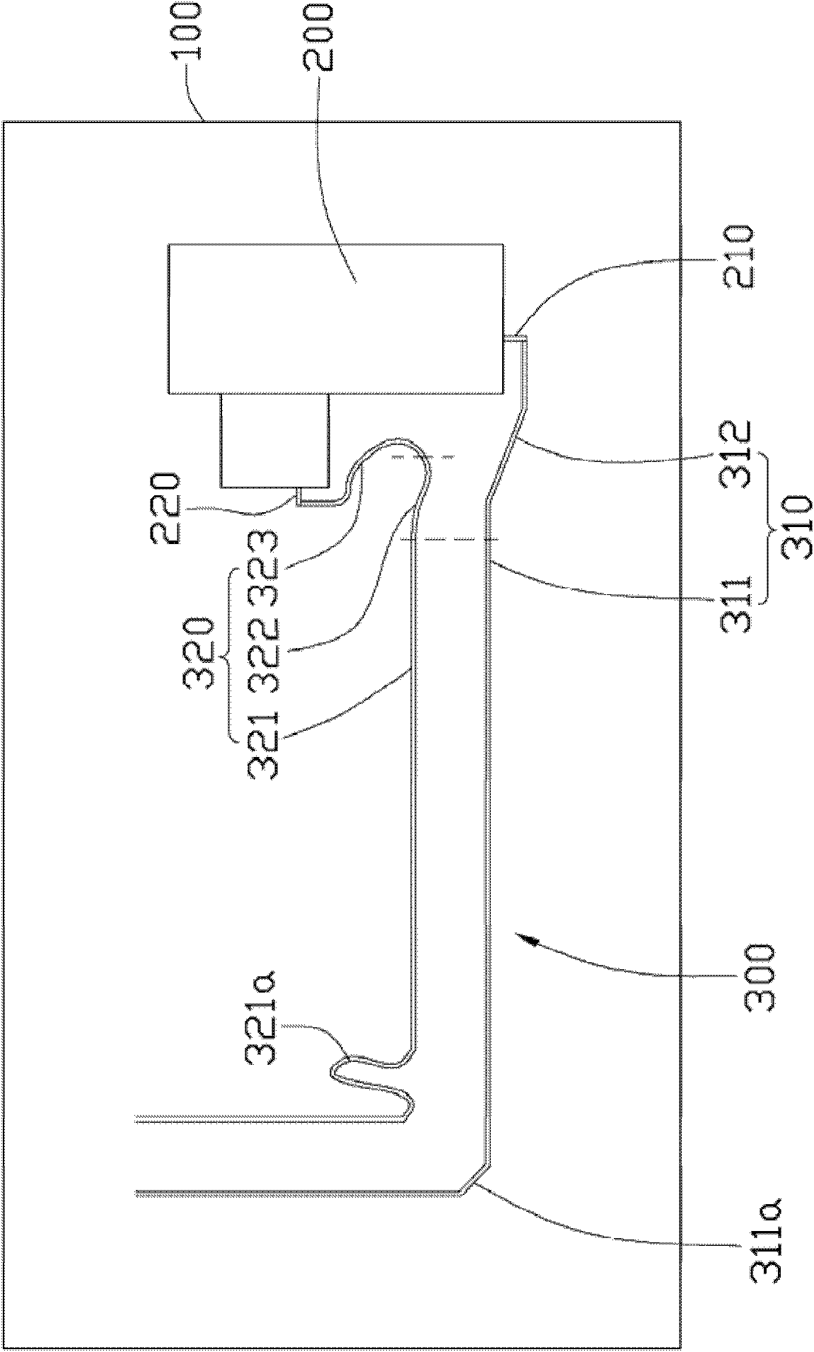
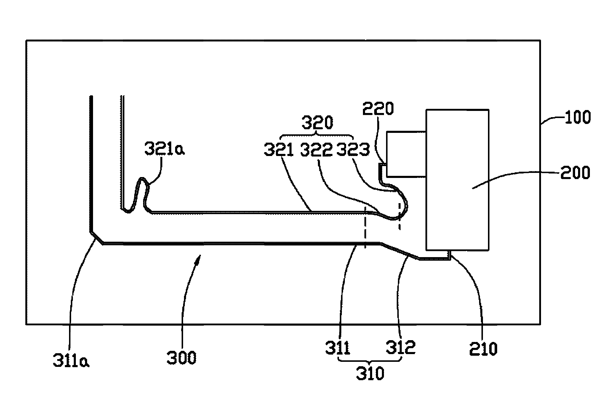
[0026] Please also refer to figure 1 and figure 2 , is a circuit board 100 provided by the present invention. The electronic components 200 are fixed on the circuit board 100 and the differential line pairs 300 are laid out. The electronic component 200 includes a first pin 210 and a second pin 220 . The differential line pair 300 includes a first differential line 310 and a second differential line 320 . The distance between the first pin 210 and the first differential line 310 is longer than the distance between the second pin 220 and the second differential line 320 .

[0027] The first differential line 310 includes a first parallel segment 311 and a first non-parallel segment 312 connected to the first parallel segment 311 . The first non-parallel segment 312 is electrically connected to the first pin 210 . The first parallel section 311 includes a first bent section 311a.

[0028] The second differential line 320 includes a second parallel section 321 , a second n...


PUM


Abstract

The invention provides a printed circuit board which includes a plurality of electronic components fixed on the printed circuit board and a differential wire pair connected among the electronic components. The differential wire pair includes a first differential wire and a second differential wire. Each differential wire includes a parallel segment and a non-parallel connected therewith. The non-parallel segment is electrically connected with the plurality of the electronic components. The parallel segments of the two differential wires are equal in length. The first differential wire includes a compensation segment. The compensation segment is connected between the non-parallel segment and the plurality of the electronic components of the first differential wire. The sum of the lengths of the compensation segment and the non-parallel segment of the first differential wire is equal to the length of the non-parallel segment of the second differential wire. The printed circuit board of the invention is provided with the compensation segment at the non-parallel segment, so two differential signals in the two differential wires can be guaranteed to enter the parallel segment at the same time, and accordingly the transmission synchronism of the differential signal in the differential wire is improved, and the differential signal is coupled more precisely in transmission. Besides, the invention also provides the differential wire wiring method.

Description

technical field [0001] The invention relates to a printed circuit board and a differential line wiring method used on the printed circuit board. Background technique [0002] In wiring design, because the two pins or two pads of electronic components cannot be in the same position, and there is not enough space near the pins or pads for parallel wiring, so two differential line pins Or near the pad is not parallel, called non-parallel segment. And non-parallel segments tend to always be unequal when routing. In the existing design, only the total lengths of the two differential lines are equal, but the problem of unequal lengths of the non-parallel segments is ignored. This prevents differential signals from entering the parallel segment through non-parallel segments of different lengths, and cannot enter the parallel segment at the same time, resulting in incomplete synchronous transmission of differential signals after entering the parallel segment. When the frequency o...

Claims


Application Information

Patent Timeline
Patent Type & Authority Applications(China)
IPC IPC(8): H05K1/02H05K1/11
CPCH05K1/0243H05K1/0248H05K2201/09263H05K1/0245H05K2201/09272
Inventor 欧光峰
Owner HONG FU JIN PRECISION IND (SHENZHEN) CO LTD
Why Eureka
Try Eureka