Compact tensioner with sustainable damping

A technology of tensioning device and damping mechanism, applied in the direction of transmission, belt/chain/gear, mechanical equipment, etc., can solve the problems of misalignment of pulleys, high manufacturing cost and damping performance

Active Publication Date: 2011-08-31
LITENS AUTOMOTIVE INC
View PDF8 Cites 18 Cited by
  • Summary
  • Abstract
  • Description
  • Claims
  • Application Information

AI Technical Summary

Problems solved by technology

Several known damping tensioners may be too expensive to manufacture, and / or may not provide consistent damping performance over the life of the tensioner, and / or may subject the pivot bushing between the arm and base to relative stress. High forces, which can cause pulley misalignment as pivot bushings wear

Method used


Image

  • Compact tensioner with sustainable damping
  • Compact tensioner with sustainable damping
  • Compact tensioner with sustainable damping

Examples


Embodiment Construction

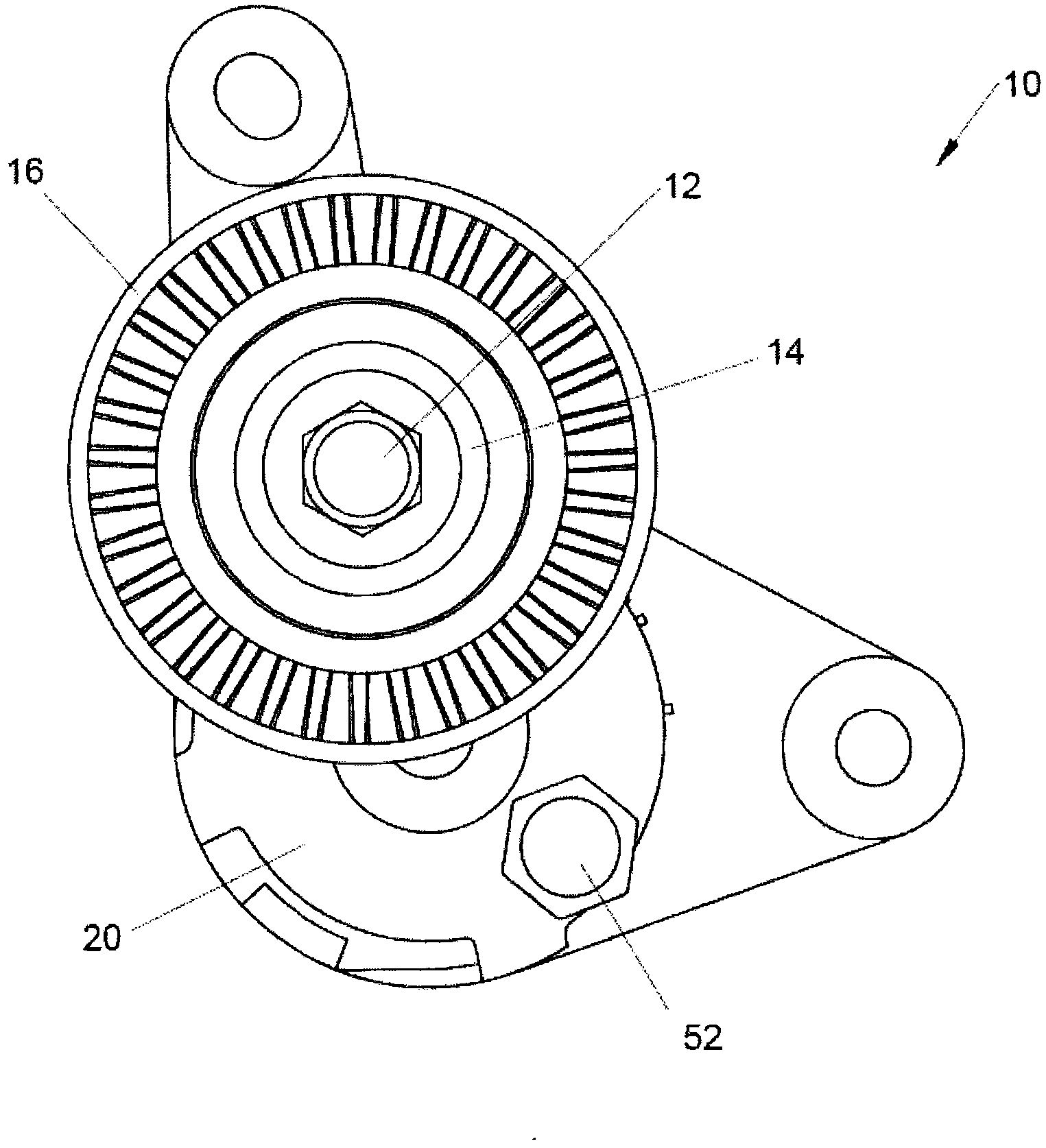
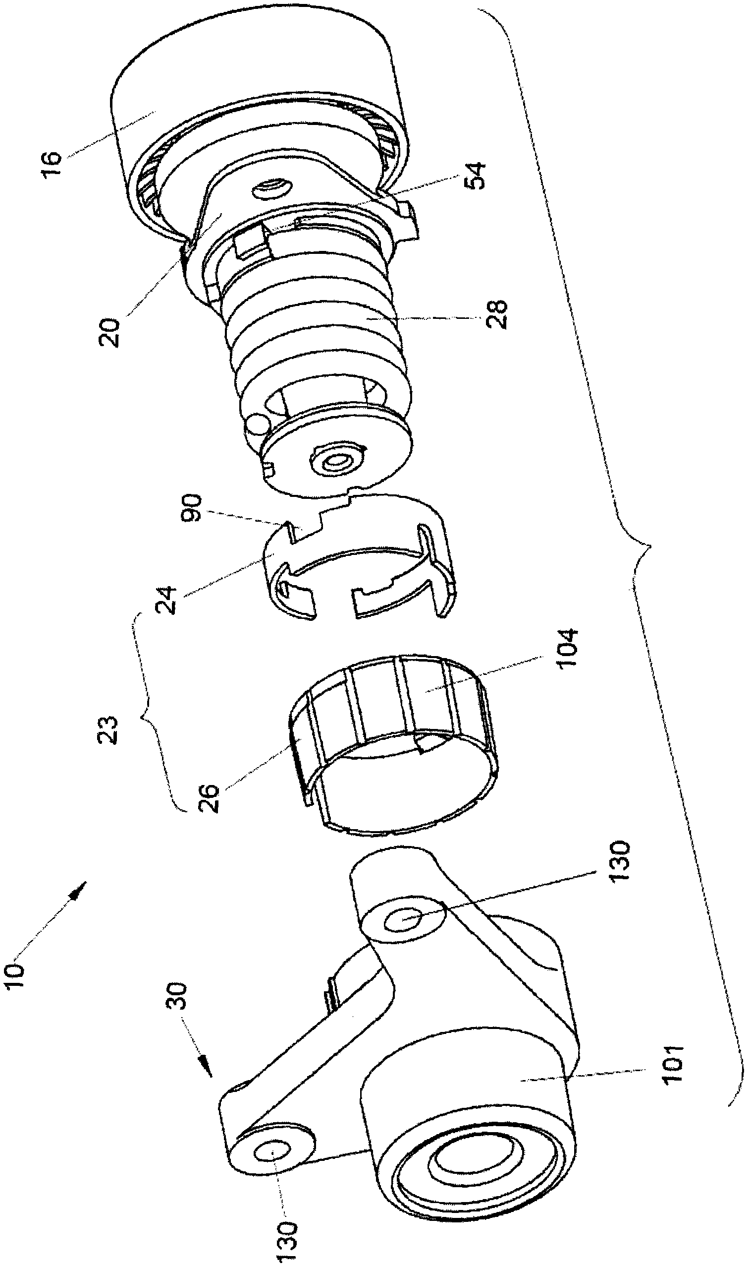
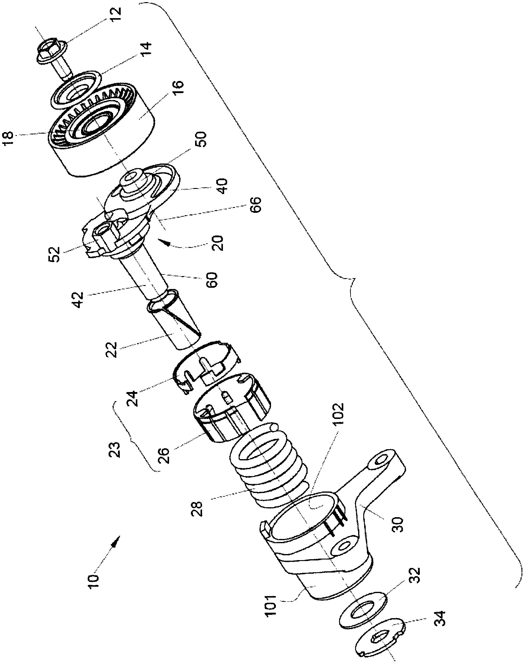
[0029] Refer to the attached Figure 1 to Figure 3, a tensioner assembly constructed in accordance with the teachings of the present disclosure is indicated generally by reference numeral 10 . The tensioner assembly 10 may include a fastener 12, a boot 14, a wheel 16, a bearing 18, an arm 20, a pivot bushing 22, a damping mechanism 23 (which may include a bushing 24 and a damping element 26), Spring 28 , bracket or base 30 , thrust washer 32 and thrust plate 34 . Fastener 12, boot 14, bearing 18, and thrust washer 32 are of generally conventional construction and need not be discussed in detail herein.

[0030] refer to Figure 2 to Figure 5 , the arm 20 may be integrally formed in a suitable process such as die casting, and may define an arm member or portion 40 and a stem member or portion 42 . Arm portion 40 may include bearing mount 50 , lift member 52 , spring reaction member 54 and spring support 56 , while stem portion 42 may include rod 60 . Bearing mount 50 may be...


PUM


Abstract

A tensioner assembly that includes a base, an arm, an opening spring (i.e., a torsion spring that opens or radially expands with increasing torque applied thereto), a spring reaction member, and a pivot bushing. The tensioner assembly is configured to orient various loads in predetermined directions. For example, a spring load can be oriented to counteract a hub load to reduce a bushing load that acts on the pivot bushing. As another example, a spring reaction force exerted by the spring reaction member can be employed by a damping mechanism to generate a grounding force that is parallel to the spring reaction force and is directed to intersect an axis about which the arm pivots relative to the base. A tensioner assembly having improved assembly characteristics is also provided.

Description

technical field [0001] The present invention generally relates to a tensioning device for tensioning an annular transmission element. Background technique [0002] Mechanical tensioners are used to automatically control the tension of endless transmission elements such as belts or chains. Typically, mechanical tensioners use an arm that pivots about a base and a torsion spring that biases the arm in a predetermined rotational direction. Torsional damping is sometimes required to ensure that ring drive elements or components driven by the ring drive system are not overstressed. Several known damping tensioners may be too expensive to manufacture, and / or may not provide consistent damping performance over the life of the tensioner, and / or may subject the pivot bushing between the arm and base to relative stress. Larger forces, which can cause misalignment of the pulleys as the pivot bushing wears down. Accordingly, there remains a need in the art for an improved damped tens...

Claims


Application Information

Patent Timeline
Patent Type & Authority Applications(China)
IPC IPC(8): F16H7/12
CPCF16H7/1218F16H2007/081F16H2007/0893F16H7/12
Inventor 马伟杰拉尔德·J·阿梅尔
Owner LITENS AUTOMOTIVE INC
Why Eureka
Try Eureka