Force feedback device and method for catheters

a feedback device and catheter technology, applied in the field of tissue ablation systems, can solve the problems of asynchronous rhythm and disruption of normal cardiac cycle, and achieve the effect of avoiding distraction

Active Publication Date: 2016-11-08
BIOSENSE WEBSTER (ISRAEL) LTD
View PDF27 Cites 84 Cited by
  • Summary
  • Abstract
  • Description
  • Claims
  • Application Information

AI Technical Summary

Benefits of technology

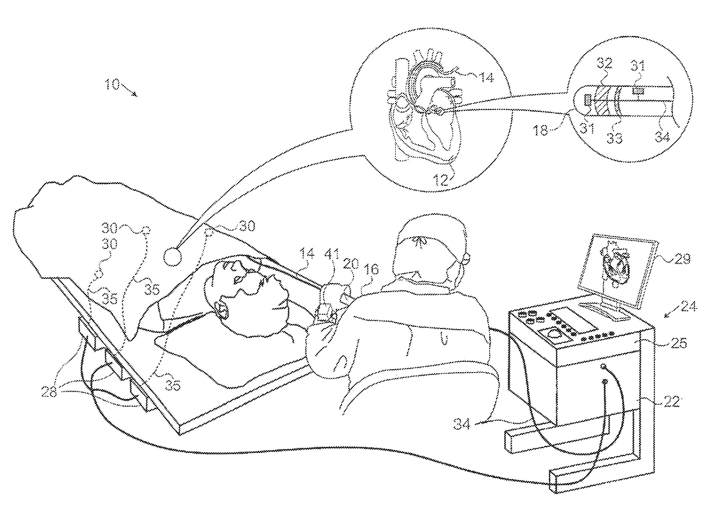
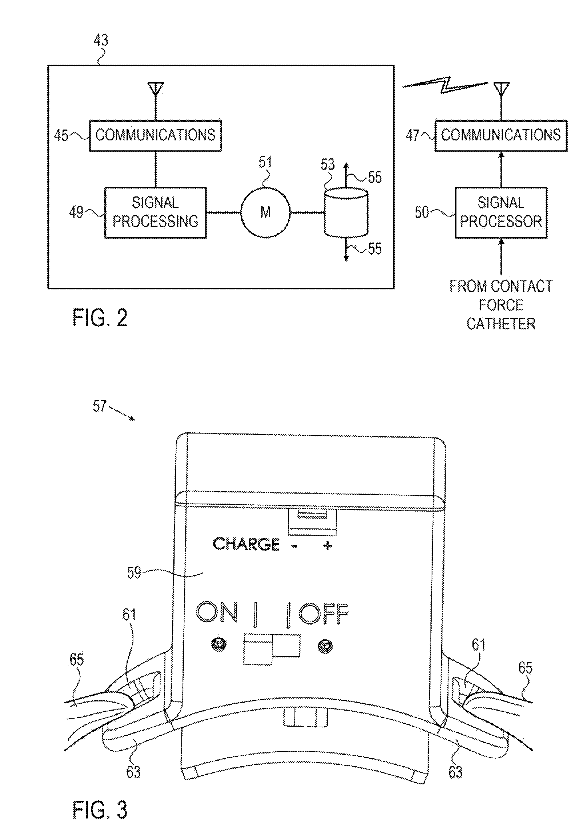
[0014]Embodiments of the present invention provide a haptic device that is worn on the body of an operator of an ablation system. The device applies direct force to the body using one or more actuators that reflect the contact force between an ablation catheter and target tissue such as the endocardial surface of the heart. The device may be embodied as a wrist bracelet, and can be dimensioned to the order of a standard wrist watch for the comfort and convenience of the operator. Contact data haptically provided to the operator by the device minimizes a need to consult a visual display and avoids distraction caused by an audio alert that might provide the contact information. The sensations produced by the haptic device are perceived by the operator as though a virtual assistant were holding his hand while he performs a medical procedure.

Problems solved by technology

Cardiac arrhythmias, such as atrial fibrillation, occur when regions of cardiac tissue abnormally conduct electric signals to adjacent tissue, thereby disrupting the normal cardiac cycle and causing asynchronous rhythm.

Method used


Image

  • Force feedback device and method for catheters
  • Force feedback device and method for catheters
  • Force feedback device and method for catheters

Examples


first alternate embodiment

[0068]Reference is now made to FIG. 6, which is a schematic view of portions of a haptic device 79 being worn about a wrist 81 of an operator, in accordance with an alternate embodiment of the invention. This embodiment operates in a similar manner to the embodiment described with respect to FIG. 2-FIG. 5. However the single actuator 67 is replaced by an array of actuators 83, 85, 87, 89, 91, 93, 95, which are distributed along the length of a strap 97 that is wrapped about wrist 81. The actuators are independently controlled as described above, e.g., by multiplexing the communication channel between the communications modules 45, 47 (FIG. 2) or by providing a plurality of communication channels. The actuators 83, 85, 87, 89, 91, 93, 95 are thus capable of individually and independently applying pressure at points on the circumference of the wrist 81 or other body part. For example, in FIG. 6 the actuator 89 is active, depressing a segment 99 of the strap 97, and thus producing an e...

second alternate embodiment

[0070]Reference is now made to FIG. 7, which is a schematic view of portions of a haptic device 107 being worn about the wrist 81, in accordance with an alternate embodiment of the invention. This embodiment has components in common with the haptic device 43 (FIG. 2), but operates using hydraulic or pneumatic methods to produce a tactile effect on the wrist 81. An inflatable cuff 109 (indicated by hatching in FIG. 7) is adapted to fit about the wrist 81 (or other body part), and is expandable from a deflated configuration indicated by broken line 111 to an inflated configuration indicated by solid line 113.

[0071]Inflation and deflation are produced by the action of a displacement hydraulic motor 115, which can be bidirectional, as shown in FIG. 7, or unidirectional. The motor operates under control of the signal processor 49, as described above with respect to FIG. 2.

[0072]When the hydraulic motor 115 inflates the cuff 109 through a hydraulic line 117, the operator perceives a press...

third alternate embodiment

[0074]Reference is now made to FIG. 8, which is a schematic view of portions of a haptic device 121 being worn about the wrist 81, in accordance with an alternate embodiment of the invention. This embodiment has components in common with the haptic device 107 (FIG. 7). However a cuff 123 is partitioned into multiple cells 125, each supplied by separate hydraulic lines 127. A hydraulic motor 129 may have individually operated ports or valves as shown in FIG. 8. Alternatively, individual hydraulic motors may supply the cells 125 via respective hydraulic lines 127. In any case, the hydraulic motor 129 or motors are controlled by the signal processor 49.

[0075]This embodiment has the same enhanced abilities as the haptic device 79 (FIG. 6), which are not repeated in the interest of brevity.


PUM


Abstract

An ablation apparatus includes a flexible probe adapted for insertion into a heart of a living subject. The probe has a distally disposed ablation electrode to be brought into contact with a target tissue in the heart, and has facilities for measuring contact force with the target tissue. The apparatus includes a transmitter, operative to transmit an indication of the contact force to a wearable device having an actuator operative to haptically stimulate the operator responsively to the indication.

Description

BACKGROUND OF THE INVENTION[0001]1. Field of the Invention[0002]This invention relates to tissue ablation systems. More particularly, this invention relates to monitoring of contact between an invasive probe and tissue within the body.[0003]2. Description of the Related Art[0004]Cardiac arrhythmias, such as atrial fibrillation, occur when regions of cardiac tissue abnormally conduct electric signals to adjacent tissue, thereby disrupting the normal cardiac cycle and causing asynchronous rhythm.[0005]Procedures for treating arrhythmia include surgically disrupting the origin of the signals causing the arrhythmia, as well as disrupting the conducting pathway for such signals. By selectively ablating cardiac tissue by application of energy via a catheter, it is sometimes possible to cease or modify the propagation of unwanted electrical signals from one portion of the heart to another. The ablation process destroys the unwanted electrical pathways by formation of non-conducting lesions...

Claims


Application Information

Patent Timeline
Patent Type & Authority Patents(United States)
IPC IPC(8): A61B18/14A61B18/00A61B5/00A61B18/12A61B5/01A61B5/053A61B17/32
CPCA61B18/1233A61B18/1492A61B5/01A61B5/053A61B5/0531A61B5/0538A61B5/6852A61B5/6885A61B5/7455A61B17/320068A61B2018/00297A61B2018/00303A61B2018/00357A61B2018/00577A61B2018/00821A61B2018/00839A61B2018/00898A61B2034/2051A61B2090/065A61B2218/002A61B2505/05A61B2017/320069A61B34/76A61B18/00A61B2018/00642A61B34/20
Inventor BONYAK, YEVGENYLEVY, DROR SHLOMOBAR-TAL, MEIRKRUPNIK, RONENKATZ, NATAN SHARON
Owner BIOSENSE WEBSTER (ISRAEL) LTD
Why Eureka
Try Eureka