Cup body of soybean milk maker without filter screen

A soymilk maker and cup technology, which is applied to milk substitutes, beverage preparation devices, household appliances, etc., can solve the problems that have not been proposed, can not meet the beating and fine grinding effect, and achieve the effect of easy cleaning and high efficiency of turbulence

Inactive Publication Date: 2011-09-07
MIDEA GRP CO LTD
View PDF1 Cites 1 Cited by
  • Summary
  • Abstract
  • Description
  • Claims
  • Application Information

AI Technical Summary

Problems solved by technology

[0009] However, neither the above-mentioned technology nor the existing netless cup technology proposes a structure

Method used


Image

  • Cup body of soybean milk maker without filter screen
  • Cup body of soybean milk maker without filter screen
  • Cup body of soybean milk maker without filter screen

Examples


Embodiment 1

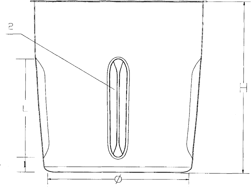
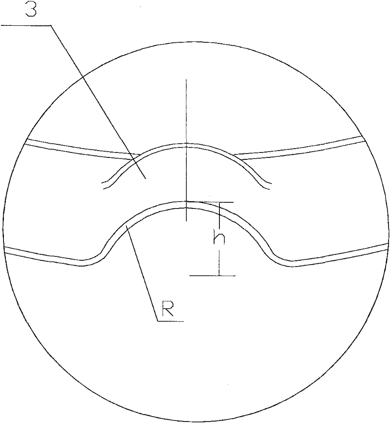
[0036] Such as Figure 1 to Figure 4 As shown, the present invention discloses a cup body of a non-net soymilk machine. The cup body is made of metal material, and several ribs 2 are arranged on the inner surface 1 thereof. The included angle α of the inner surface 1 is 120°-145°. Here, the angle between the two surfaces of the flow blocking surface 3 and the inner surface 1 passes through the tangent of the inner surface 1 at the intersection of the flow blocking surface 3 and the inner surface 1, and the top of the flow blocking surface 3 and the flow blocking surface 3 and the inner surface 1 The angle between the connecting chords of the intersection points is determined, such as Figure 7 shown.

[0037] The installation position of the soya-bean milk maker cutter is located at the central axis of the cup body and close to the bottom position, which is the installation position of the general existing soymilk maker cutter. Under the agitation of the cutter placed on th...

Embodiment 2

[0046] This embodiment is further limited on the basis of Embodiment 1, specifically, the included angle α between the flow blocking surface 3 of the rib 2 and the inner side surface 1 of the cup is 125°-135°. Utilizing the turbulence effect of the ribs 2 described in Embodiment 1 and the direction of rotation of the bean grains, this embodiment further accurately positions the bean grains hitting the knife when they rebound from the choke surface 3 . In this embodiment, when the included angle between the choke surface 3 and the inner surface 1 is 125°-135°, under the action of the rib 2 choke surface 3, if the direction of rotation of the liquid flow is counterclockwise, the bean grains will To the central position of the cutter, which greatly increases the probability of bean grains colliding with the cutter and improves the turbulence effect.

Embodiment 3

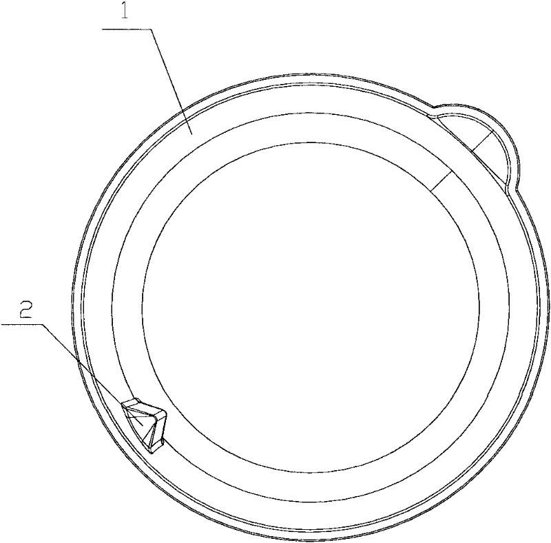
[0048] This embodiment is further limited on the basis of Embodiment 1, specifically, the number of ribs 2 is 3 to 4, such as Figure 5 shown. In this embodiment, the number of ribs 2 is set at 3 to 4, and they are evenly distributed on the side surface 1 of the cup body. It is driven to move in the circumferential direction for the next step of disturbing the flow, which improves the defect that the flow disturbance efficiency of only one rib is not too high, and also improves the fact that when there are five ribs, the beans can only be hit near the cutter without being hit. Can not hit the defect in the center of the tool, so this embodiment can greatly improve the effect of turbulence.


PUM

PropertyMeasurementUnit
Angleaaaaaaaaaa
The inside diameter ofaaaaaaaaaa
Height haaaaaaaaaa

Abstract

The invention belongs to the technical field of a soybean milk maker without a filter screen, and particularly discloses a cup body of a soybean milk maker without a filter screen, wherein the cup body is used for solving the defect that the turbulent flow effect of the existing soybean milk maker without the filter screen is not good. The specific scheme is as follows: the cup body is made of a metal material; the inner side face (1) of the cup body is provided with a plurality of steel bars (2); the included angle of the stream resisting face (3) of each steel bar and the inner side face (1) is 120-145 degrees; the number of the steel bars (2) is 1-5; and when the number of the steel bars is more than 2, the steel bars (2) are evenly distributed on the inner side face (1). The cup body provided by the invention can achieve an efficient turbulent flow effect, and can effectively satisfy the fine grinding effect needed in pulping.

Description

technical field [0001] The invention belongs to the technology of a soybean milk maker, in particular to a cup body of a soybean milk maker. Background technique [0002] At present, soybean milk machine has been widely used, and it is often used in household soybean pulping to provide people with healthy soybean milk drink. [0003] Existing soya-bean milk machine generally comprises following parts: [0004] Cup body: used to hold water or soybean milk, the "upper water level" line and "lower water level" line are marked on the cup body to regulate the amount of water added to the cup body; [0005] Machine head: The machine head is the assembly of the soybean milk machine. Its shell is divided into an upper cover and a lower cover. The lower cover is used to install the main components, including the computer board, transformer and beating motor located in the lower cover. The lower part has a blade, a mesh cover, an anti-overflow electrode, a temperature sensor, and an...

Claims


Application Information

Patent Timeline
IPC IPC(8): A23C11/10A47J31/44
Inventor 李前荣
Owner MIDEA GRP CO LTD
Why Eureka
Try Eureka