Intelligent illuminating method and device for road tunnel

A technology for intelligent lighting and road tunnels, which is applied to lighting devices, components of lighting devices, circuit layout, etc. It can solve the problems of driver's speed and distance judgment deviation, brightness cannot be adjusted, and safety hazards are not solved. Achieve the effects of reducing lamp loss, low production cost, and easy implementation

Inactive Publication Date: 2011-09-07
GUIZHOU UNIV
View PDF2 Cites 31 Cited by
  • Summary
  • Abstract
  • Description
  • Claims
  • Application Information

AI Technical Summary

Problems solved by technology

Due to the long distance of the current highway tunnels, it is usually necessary to install more tunnel lights, and because these tunnel lights are usually controlled in a unified way, and their brightness cannot be adjusted, because the lighting brightness of the tunnel lights inside the tunnel is different from that outside the tunnel. There may be differences between the natural light brightness. Therefore, when the car enters the tunnel, due to the large change in light, the driver will not be able to adapt for a while, feeling that the entrance of the tunnel is very dark, and cannot distinguish the road conditions, resulting in a "black hole effect", which will make it easy for the driver. Deviations in the judgment of speed and distance, bringing serious hidden dangers
However, if only the brightness of the lighting in the tunnel is increased, a "white hole effect" may occur when the car leaves the tunnel, and increasing the brightness of the lighting in the tunnel also means an increase in power consumption, and it does not solve the existing safety hazards

Method used


Image

  • Intelligent illuminating method and device for road tunnel
  • Intelligent illuminating method and device for road tunnel
  • Intelligent illuminating method and device for road tunnel

Examples


Embodiment Construction

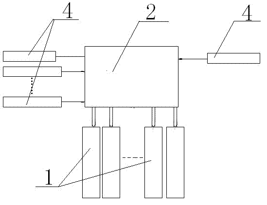
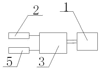
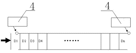
[0027] Embodiments of the present invention: an intelligent lighting method for road tunnels, using LED lights as tunnel lights in the tunnel; a controller is installed on each tunnel light, but the controller is also subject to brightness signals and switches sent by the central controller. Signal control; collect the natural light brightness information outside the tunnel through the sensor, and send the information to the central controller; the central controller sends the corresponding brightness control instructions to the tunnel lights of each section based on the information received, and the controller of the tunnel lights On the one hand, it accepts the brightness control information of the central controller, and on the other hand, collects the lighting information of the road section, and adjusts the brightness quickly after comprehensive processing by the controller to meet the brightness requirements of safety lighting, so as to realize the purpose of adjusting the...


PUM


Abstract

The invention discloses an intelligent illuminating method and an intelligent illuminating device for road tunnels. The method comprises the following steps that: natural light brightness information outside the tunnel is acquired by a sensor; the acquired information is sent to a central controller; the central controller sends a brightness adjusting instrument to lamps according to the received information; a lamp controller is mounted on each tunnel lamp; illuminating brightness information of the corresponding tunnel road section is acquired by the sensor; and the lamp controller integrates the acquired information with the brightness control instruction sent by the central controller for adjusting the illuminating brightness of each tunnel lamp so that the illuminating brightness can meet the illumination requirements and the illuminating brightness of each illuminating section in the tunnel is adjusted. By the invention, a black-hole effect and a white-hole effect at the exit and entrance of the tunnel are eliminated; the problems of excessive illumination and unavailable illumination of the tunnel lamp in the tunnel are solved; the traffic safety on the pavement is improved; the lamp consumption is reduced; and the operation and maintenance cost of the tunnel is reduced.

Description

technical field [0001] The invention relates to a road lighting method and device, in particular to an intelligent lighting method and device for a road tunnel. Background technique [0002] At present, with the development of highway construction, the number of long tunnels and extra-long tunnels is increasing, and the lighting problems of highway tunnels also follow. Due to the long distance of the current road tunnels, more tunnel lights are usually set up, and because these tunnel lights are usually controlled in a unified way, and their brightness cannot be adjusted, because the lighting brightness of the tunnel lights inside the tunnel is different from that outside the tunnel. There may be differences in the brightness of natural light. Therefore, when the car enters the tunnel, due to the large change in light, the driver will not be able to adapt for a while, and the hole will feel very dark, and the road conditions cannot be distinguished, resulting in a "black hol...

Claims


Application Information

Patent Timeline
Patent Type & Authority Applications(China)
IPC IPC(8): H05B37/02F21V23/04F21W131/101F21Y101/02F21Y115/10
CPCY02B20/48Y02B20/40
Inventor 李良荣潘鸣
Owner GUIZHOU UNIV
Why Eureka
Try Eureka