Z axis elastic distance servo system used for laser processing

A laser processing and follow-up system technology, applied in laser welding equipment, metal processing equipment, manufacturing tools, etc., can solve problems such as economic loss, damage to the laser head, and inaccurate laser head distance, so as to achieve a wide range of applications and avoid errors. Effects of collision, avoidance of response hysteresis effect

Inactive Publication Date: 2011-09-14
武汉工研光学科学技术股份有限公司
View PDF4 Cites 42 Cited by
  • Summary
  • Abstract
  • Description
  • Claims
  • Application Information

AI Technical Summary

Problems solved by technology

The disadvantage of the non-contact capacitive sensor servo system is that due to the irregularity of the cutting path on the surface of the workpiece and the quality of the connection circuit of the capacitive sensor, the execution motor controls the distance between the laser head and the surface of the workpiece. The danger of the laser head colliding with the workpiece, or even damage the laser head, resulting in major economic losses
In addition, because the distance signal generated by the capacitive sensor needs to be processed, and then the laser head is controlled to rise or fall according to the processed distance signal, there is a response lag effect in the signal processing process, so there will be a certain delay in the rise or fall of the laser head
Furthermore, the non-contact capacitive sensor servo system is only suitable for the case where the workpiece to be processed is a metal part, and the distance measuring function cannot be realized for the cutting of non-metallic parts

Method used


Image

  • Z axis elastic distance servo system used for laser processing
  • Z axis elastic distance servo system used for laser processing
  • Z axis elastic distance servo system used for laser processing

Examples


Embodiment Construction

[0015] The present invention will be further described in detail below in conjunction with the accompanying drawings and specific embodiments.

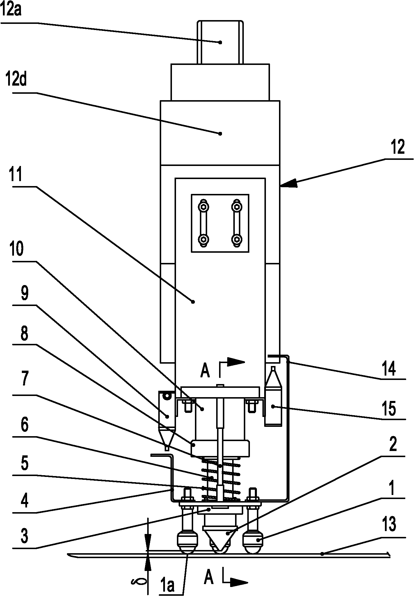
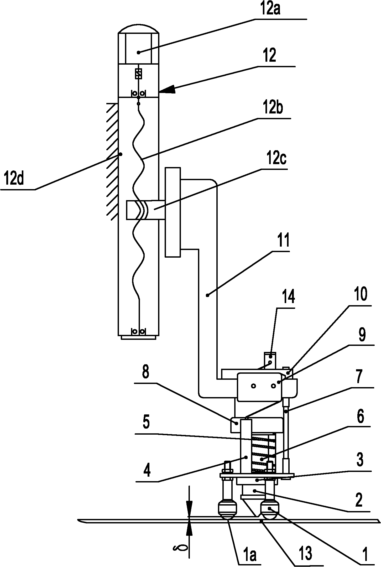
[0016] Such as Figure 1 to Figure 3 As shown, the Z-axis elastic fixed-distance follow-up system for laser processing of the present invention includes a laser head 2 of the laser processing equipment, and a Z-axis actuator 12 that drives the laser head 2 to move vertically. The Z-axis actuator 12 includes a fixed frame 12d. The fixed frame 12d is provided with a ball screw 12b connected to the drive motor 12a. The ball screw 12b is provided with a ball nut 12c that moves with it, and the ball nut 12c is connected with the support 11. . The driving motor 12a can be a servo motor or a stepping motor.

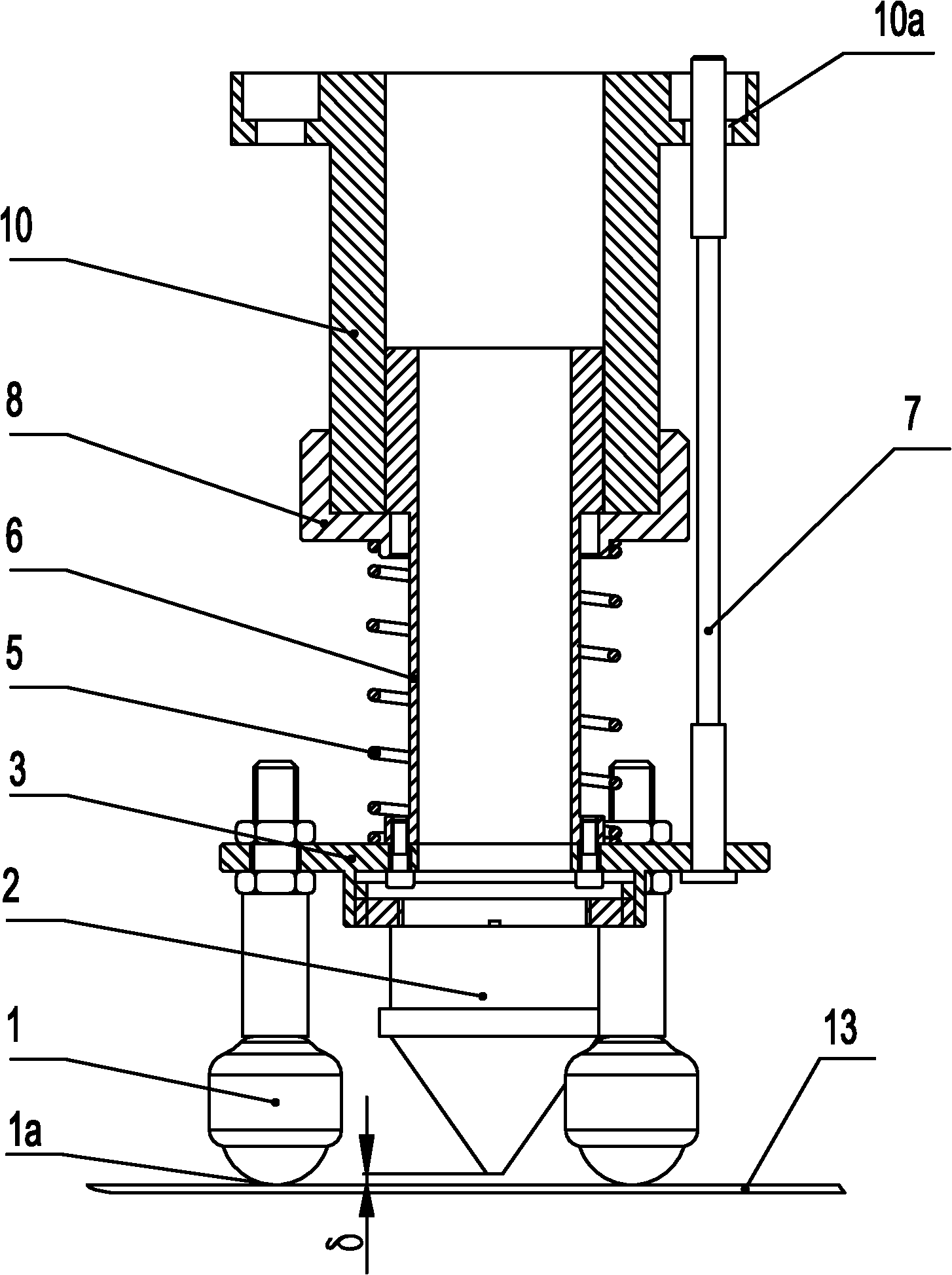
[0017] The bracket 11 is an L-shaped bracket, its vertical surface is fixedly connected with the ball nut 12c through a connecting piece, and the fixed guide sleeve 10 arranged vertically is installed and fixed in the middle of its ho...


PUM


Abstract

The invention discloses a Z axis elastic distance servo system used for laser processing, wherein a Z axis actuating mechanism is connected to a bracket; the bracket is provided with a fixed guiding sleeve and upper and lower limiting switches; a sliding guiding sleeve which can extend downwards is arranged in the fixed guiding sleeve; the lower end of the fixed guiding sleeve is provided with ananti-dropping cover; the lower end of the sliding guiding sleeve is provided with a connecting flange; a returning spring is arranged between the connecting flange and the anti-dropping cover; upper and lower limiting rods which are corresponding to the upper and lower limiting switches are arranged on the connecting flange; a laser head is fixed under the connecting flange and is aimed at a processed workpiece; a universal rolling ball head which can move on the surface of the processed workpiece is fixed under the connecting flange; and a constant vertical interval is kept between a light outlet of the laser head and the lower end of the universal rolling ball head. The Z axis elastic distance servo system can be used for realizing the elastic floatation of the laser head in a defined scope and realizing the quick ascending and descending of the laser head out of the preset scope by using the limiting switches to control a driving motor, thereby ensuring that the laser beam is focused on the surface of the processed workpiece all the time.

Description

technical field [0001] The invention relates to the technical field of non-contact processing, in particular to a Z-axis elastic fixed-distance servo system for laser processing. Background technique [0002] In the field of non-contact processing, such as laser cutting, the focal point of the laser beam should be located on the surface of the workpiece. Once the defocus phenomenon occurs, that is, the focal point of the laser beam deviates from the surface of the workpiece, the laser processing power density will be greatly lost, and the attenuation curve will change geometrically. Therefore, ensuring that the focus point of the laser beam is located on the surface of the workpiece, that is, keeping the distance between the laser head and the surface of the workpiece constant, is the key technology of laser cutting. [0003] In order to ensure that the focal point of the laser beam is located on the surface of the workpiece, the Z-axis follow-up system of the prior art tak...

Claims


Application Information

Patent Timeline
Patent Type & Authority Applications(China)
IPC IPC(8): B23K26/08
Inventor 王晓辉石敏陈和平陈晓泉卢治孟丽金彦
Owner 武汉工研光学科学技术股份有限公司
Why Eureka
Try Eureka