Rod end knuckle bearing and rod end knuckle bearing assembling equipment and assembling method

A rod end joint bearing and assembly equipment technology, applied in the direction of bearings, bearing components, shafts and bearings, etc., can solve problems such as the damage of the anti-corrosion coating on the surface of the rod end body, avoid corrosion failure, ensure service life, and prolong use. effect of life

Pending Publication Date: 2021-03-30
台州科锦轴承有限公司
View PDF9 Cites 1 Cited by
  • Summary
  • Abstract
  • Description
  • Claims
  • Application Information

AI Technical Summary

Problems solved by technology

[0006] The purpose of the present invention is to provide a rod end joint bearing to solve the technical problem in the prior art that the anti-corrosion coating on the surface of the rod end body is destroyed when the end face of the rod end body is cut into a V-shaped notch to realize the locking of the bead At the same time, the present invention also provides a rod end joint bearing assembly device to solve the problem that the assembly device in the technology needs to cut a V-shaped notch on the end face of the rod end body to realize the locking of the bead and cause the anti-corrosion coating on the surface of the rod end body to be damaged technical problems; at the same time, the present invention also provides a rod end joint bearing assembly method

Method used


Image

  • Rod end knuckle bearing and rod end knuckle bearing assembling equipment and assembling method
  • Rod end knuckle bearing and rod end knuckle bearing assembling equipment and assembling method
  • Rod end knuckle bearing and rod end knuckle bearing assembling equipment and assembling method

Examples


specific Embodiment

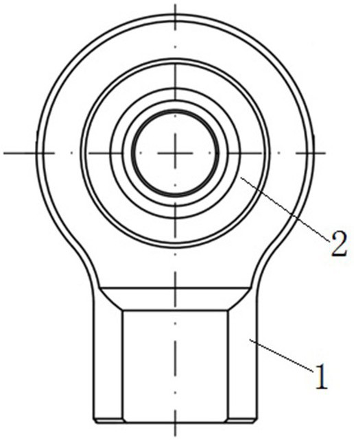
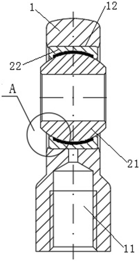
[0047] Such as Figure 1 to Figure 3 As shown, the rod end joint bearing in this embodiment includes a rod end body 1 and a bearing assembly 2. One end of the rod end body 1 is provided with an eye hole 12, and the other end is provided with a threaded hole 11. The center line of the eye hole 12 is aligned with the threaded hole 11. The center lines of the rods intersect vertically, and the rod body is made of low-alloy high-strength steel 16Mn. In order to improve the corrosion resistance of the rod end body 1, a Dacromet surface coating process is used on the outer surface of the rod end body 1 to form an anti-corrosion layer. Moreover, the threaded hole 11 at the corresponding end of the rod end body 1 adopts a fine-pitch thread to meet the fine-pitch adjustment in the narrow space of the solar tracking bracket. Of course, for the rod end body 1 , in other embodiments, the anti-corrosion layer can also be a galvanized layer.

[0048] The bearing assembly 2 includes an inne...

specific Embodiment 1

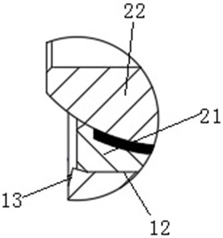
[0053] as 1 to Figure 5 As shown, the rod end joint bearing assembly equipment in this embodiment includes two extrusion dies. In this embodiment, the two extrusion dies are the first extrusion die and the second extrusion die, and the two extrusion dies are along the vertical direction Space distribution, the up and down direction here is the extrusion direction, the two extrusion dies can move towards each other along the extrusion direction, in fact, the extrusion direction is consistent with the extension direction of the center line of the rod end body 1 eye hole 12 of the rod end joint bearing , the two extrusion dies cooperate to lock the bearing assembly 2 into the eye hole 12 of the rod end body 1, and push the end faces of the two hole edges of the extrusion eye hole 12, forcing the hole to form an extruded inclined end face along the end face, The extruded inclined end face is gradually inclined towards the outer ring 22 of the bearing assembly 2 along the radial d...

specific Embodiment 2

[0067] The main difference between it and Embodiment 1 is that in Embodiment 1, only the second extrusion die is an active extrusion die, and the outer ring pushing part on the active extrusion die is elastically floating along the extrusion direction. In this embodiment, the two extrusion dies are both active extrusion dies, that is, the structures of the two extrusion dies are the same as the second extrusion die in Embodiment 1 above, and will not be repeated here.


PUM


Abstract

The invention relates to a rod end knuckle bearing and rod end knuckle bearing assembling equipment and method. The rod end knuckle bearing is characterized in that an anti-corrosion layer is arrangedon the outer surface of a rod end body; the outer ring of a bearing assembly is inserted into an eye hole of the rod end body in a matched manner; hole edges are arranged at the two ends of the eye hole respectively and located at the axial outer sides of the corresponding ends of the outer ring respectively; and the end face of each hole edge is extruded to form an annular extruded inclined endface, the extruded inclined end faces gradually incline towards the outer ring in the radial direction of the eye hole, so that each hole edge extends inwards in the radial direction of the eye hole to deform to form a closing-in hole edge, and the two closing-in hole edges extrude the outer ring to lock and fix the outer ring in the eye hole. The end faces of the hole edges at the two ends of theeye hole are extruded to deform, so that the hole edges form the closing-in hole edges, and the outer ring of the bearing assembly is locked and fixed. In the assembling process, a V-shaped cutting notch does not need to be formed in the rod end body, damage to the anti-corrosion layer on the surface of the rod end body can be effectively reduced, and the service life of the rod end knuckle bearing is guaranteed.

Description

technical field [0001] The invention relates to a rod-end joint bearing, assembly equipment and an assembly method for the rod-end joint bearing. Background technique [0002] With the vigorous development of the photovoltaic industry, solar brackets are also constantly changing. In order to maximize the photoelectric conversion efficiency of photovoltaic panels, they are equipped with light tracking devices. The tracking brackets use joint bearings, so that the tracking brackets can automatically track sunlight. Photovoltaic modules are usually installed outdoors, and they have to experience all kinds of severe weather such as heavy rain, typhoon, earthquake, etc., requiring joint bearings to have high strength and corrosion resistance, but there are more or less problems in the existing technologies. [0003] In view of such situations, in the prior art, an anti-corrosion layer is mainly provided outside the body of the rod end, for example, galvanized on the body surface ...

Claims


Application Information

Patent Timeline
IPC IPC(8): F16C23/04F16C43/02
CPCF16C23/043F16C43/02
Inventor 占松华曾伟林张平孔静静赵银龙
Owner 台州科锦轴承有限公司
Why Eureka
Try Eureka