
Motor vehicle brake device of clutch and brake system

A braking device and motor vehicle technology, applied in the direction of foot-operated starting devices, control devices, vehicle components, etc., can solve problems such as life, property loss, energy waste, and impact on life, and achieve improved driving safety, comfortable and convenient operation, and The effect of protecting people's lives

Inactive Publication Date: 2011-09-14
孙厚杰
View PDF5 Cites 9 Cited by
  • Summary
  • Abstract
  • Description
  • Claims
  • Application Information

AI Technical Summary

Problems solved by technology

[0002] At present, the clutch pedals, brake pedals and accelerator pedals of various motor vehicles and their systems are independent of each other, and their actions and operations are independent of each other. Power consumption, loss, energy waste
In particular, the two pedals of brake and acceleration, which have opposite logic and actions, are adjacent to each other and are operated by the right foot. In an emergency, especially for novices, they often "do not choose the road" and are very easy to misuse, resulting in contradictory actions. The result is the opposite, resulting in loss of life and property, delay in official and private affairs

Method used


Image

  • Motor vehicle brake device of clutch and brake system
  • Motor vehicle brake device of clutch and brake system
  • Motor vehicle brake device of clutch and brake system

Examples


Embodiment Construction

[0020] The present invention will be described in detail below in conjunction with the accompanying drawings.

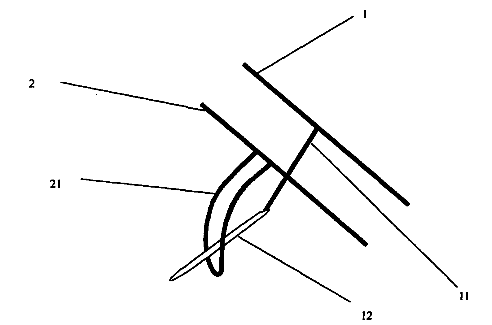
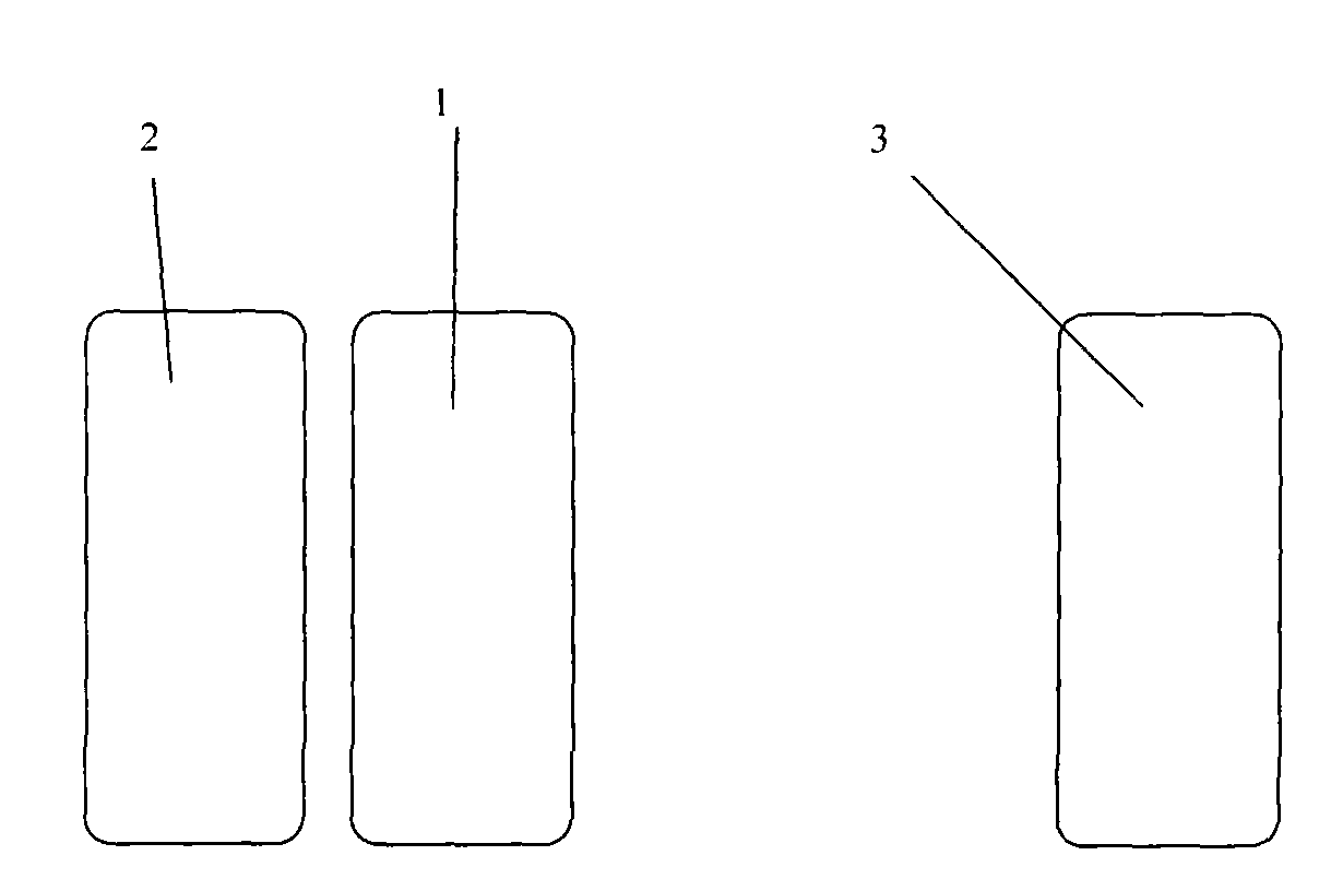
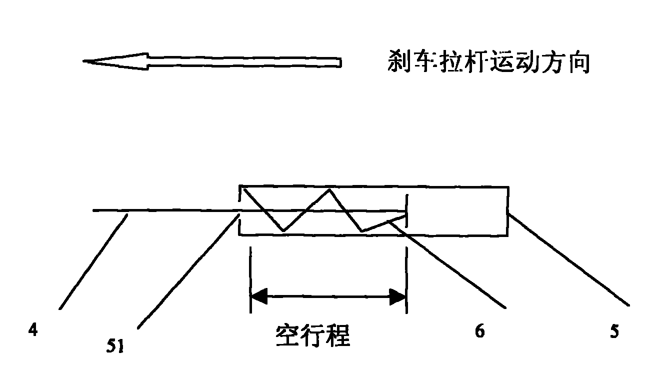
[0021] Such as Figure 1-2 As shown, it is an embodiment of the present invention, which is an implementation method of the "disengagement brake system motor vehicle brake device" of the present invention, which is characterized in that the clutch pedal 2 is adjacent to the brake pedal 1, and their rotation axes are coaxial and vertical After the brake pedal 1 and the clutch driving rod 11 under it are bent by 90° (or other powerful shapes for the implementation of the program), the clutch driving rod 12 is formed and inserted into the driven rod 21 under the clutch pedal. The driven rod 21 is vertical On the clutch pedal and below it is a section of hollow arc whose center is the rotating shaft of the clutch pedal. The hollow shape can accommodate the travel track of the clutch drive rod 12 and make it move freely. The distance between the clutch drive rod 12 inser...


PUM


Abstract

The invention provides a motor vehicle brake device of a clutch and brake system. A fit linkage principle and a structural principle of a clutch system, a brake system and an acceleration system, and arrangement and operating methods of a clutch pedal, a brake pedal and an acceleration pedal are provided. During motion, the brake system is linked with the clutch system and independent of the acceleration system; during the motion, the clutch system is not linked with the brake system and independent of the acceleration system; the clutch pedal and the brake pedal are operated by the left foot of a driver; and the acceleration pedal is operated only by the right foot of the driver. Meanwhile, the invention provides an optimized scheme, in which the brake pedal and the clutch pedal are integrated into a clutch and brake pedal; the upper half travel of the clutch and brake pedal finishes the motion of a clutch, while the lower half travel begins and finishes the motion of the brake system; and the clutch and brake pedal is operated by the left foot of the driver, while the acceleration pedal is operated by the right foot of the driver, so the device is simple and clear, safe and reliable, easy to learn, remember and operate, and extremely low in maloperation rate. Meanwhile, the clutch and brake pedal is designed to structurally comprise a clutch pull rod and a brake pull rod.

Description

technical field [0001] The invention relates to a motor vehicle braking device, in particular to a principle of the motor vehicle braking device and an application example thereof. Background technique [0002] At present, the clutch pedals, brake pedals and accelerator pedals of various motor vehicles and their systems are independent of each other, and their actions and operations are independent of each other. Power consumption, loss, and energy waste. In particular, the two pedals of brake and acceleration, which have opposite logic and actions, are adjacent to each other and are operated by the right foot. In an emergency, especially for novices, they often "do not choose the road" and are very easy to misuse, resulting in contradictory actions. The result is the opposite, resulting in loss of life and property, and delays in official and private affairs. Contents of the invention [0003] The purpose of the present invention is to provide a motor vehicle braking de...

Claims


Application Information

Patent Timeline
IPC IPC(8): B60T7/06B60K23/02
CPCB60K23/02B60T7/06
Inventor 孙厚杰
Owner 孙厚杰
Learn More