LED linear light source and reading apparatus

A linear light source and rod-shaped technology, applied in the field of LED linear light source and reading device, can solve the problem that it is difficult to shorten the total length of the light guide, and achieve the effect of a compact linear light source

Inactive Publication Date: 2014-11-26
USHIO DENKI KK
View PDF5 Cites 0 Cited by
  • Summary
  • Abstract
  • Description
  • Claims
  • Application Information

AI Technical Summary

Problems solved by technology

Therefore, it is difficult to shorten the overall length of the light guide

Method used


Image

  • LED linear light source and reading apparatus
  • LED linear light source and reading apparatus
  • LED linear light source and reading apparatus

Examples


Embodiment 1

[0053] figure 1 The first embodiment of the LED linear light source of the present invention is shown. The light guide body 1 is made of translucent acrylic resin and has a total length of 320 mm. figure 1 (a) shows a side view seen from the light incident portion 10 of the light guide 1 perpendicular to the optical axis direction, figure 1 (b) shows a measurement configuration diagram including the light receiving element 32, figure 1 (c) means figure 1 (b) A-A' sectional view.

[0054] The light guide 1 is composed of an upper surface 3 including an emission surface 2 , a lower surface 7 opposite to the upper surface 3 , and a side surface 8 connecting the upper surface 3 and the lower surface 7 . Reflecting surface 6 constituted by concave portion 4 and convex portion 5 is formed on lower surface 7 .

[0055] The light source 12 is composed of a light emitting diode 13 placed on a substrate; a hemispherical sealing body 14 sealing its outer periphery; and a reflec...

Embodiment 2

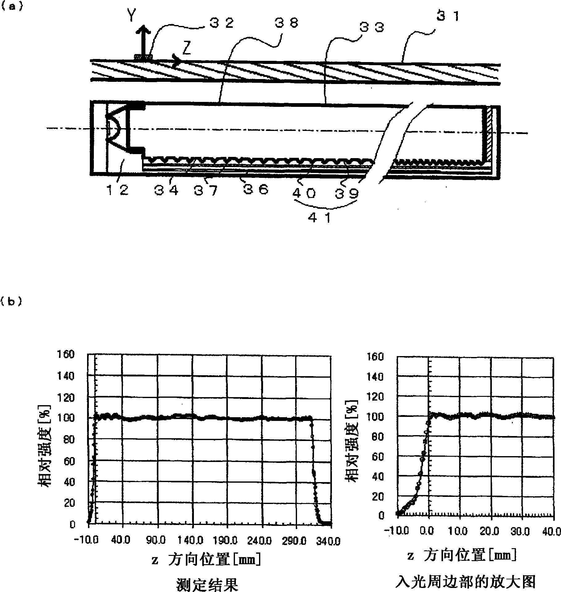
[0064] figure 2 It is the second embodiment of the LED linear light source of the present invention. The difference from the first embodiment is that a translucent diffusion sheet 37 is interposed between the lower surface 34 and the side surface 35 of the light guide body 33 and the diffusion reflection member 36 . As the translucent diffusion sheet 37, for example, 25MBC manufactured by Kimoto Co., Ltd. or the like can be used.

[0065] exist figure 2 In (a), the small rectangular member mounted on the glass 31 represents the light receiving element 32 . The light receiving element 32 can move in the Z direction, and the intensity distribution on the glass 31 can be measured.

[0066] figure 2 (b) shows the intensity distribution on the glass 31 . The vertical axis in this figure represents the relative intensity of light. Specifically, it shows that the measurement glass 31 on the original side is equivalent to and figure 1 (b) The intensity value of light at the...


PUM


Abstract

An LED linear light source includes an approximately rod-shaped light guiding member, at an end portion of which an LED is provided. The light guiding member is in an approximately arc shape in a cross sectional view taken perpendicular to an optical axis. The light guiding member has an upper face including a light emission face for emitting light and a lower face including a reflective face, which are arranged in parallel. A diffusing member diffuses light provided on part of an outer circumferential face adjacent to a light entering end face of the light guiding member. A light absorption member is provided in an outside of the light guiding member near at an end portion thereof.

Description

technical field [0001] The invention relates to an LED linear light source and a reading device used in a manuscript illuminating device. In particular, it relates to an LED linear light source and a reading device in which LEDs are arranged at the end of a light guide. Background technique [0002] Conventionally, a technology using a light emitting diode (LED) as a light source of a document lighting device is known. This technology is divided into the following two types: an array type in which a plurality of LEDs are arranged across the entire width direction of the document surface; The type of radiation transmitted to the light guide. Recently, with the increase in output of LEDs, the type using a light guide has attracted attention. [0003] Examples of linear light sources using light guides include Japanese Patent Application Laid-Open No. 11-134918. [0004] Figure 7 Represents the linear light source described in the above publication. The LED 71 is arranged...

Claims


Application Information

Patent Timeline
Patent Type & Authority Patents(China)
IPC IPC(8): F21V8/00F21V13/00F21Y101/02
CPCG02B6/001H04N1/0289H04N1/02835
Inventor 龟井宏市至极稔横川佳久金端祥宽
Owner USHIO DENKI KK
Why Eureka
Try Eureka