Heat exchange tube and smoke heat exchanger

A flue gas heat exchanger and heat exchange tube technology, applied in the field of flue gas heat exchangers and heat exchange tubes, can solve problems such as low heat exchange efficiency, small heat exchange area, and tearing of connection positions, and achieve improved heat exchange Efficiency, the effect of increasing the heat exchange area

Active Publication Date: 2012-05-30
FUJIAN LONGKING
View PDF1 Cites 0 Cited by
  • Summary
  • Abstract
  • Description
  • Claims
  • Application Information

AI Technical Summary

Problems solved by technology

[0006] First, in the above structure, such as figure 1 and figure 2 As shown, the axial sides of the heat exchange tube are connected with axial heat exchange fins 2′, and the heat exchange tube adopts a membrane heat exchange structure, which has a small heat exchange area, resulting in low thermal efficiency;
[0007] Second, when flue gas heat exchange occurs, such as figure 2 As shown, the distance between adjacent heat exchange tube sections 1' will increase due to thermal expansion, and at this time the axial heat exchange fins 2' are basically does not change, which will cause tearing at the connection position between the axial heat exchange fin 2' and the heat exchange tube section 1';
[0008] Third, when flue gas heat exchange occurs, such as figure 1 As shown, in the axial direction along the heat exchange tube section 1', since the axial heat exchange fins 2' between the heat exchange tube sections 1' are of integral structure, when the axial heat exchange fins 2' thermally expand due to heat , in the axial direction of the heat exchange tube section 1', the axial heat exchange fins 2' may also be broken

Method used


Image

  • Heat exchange tube and smoke heat exchanger
  • Heat exchange tube and smoke heat exchanger
  • Heat exchange tube and smoke heat exchanger

Examples


Embodiment Construction

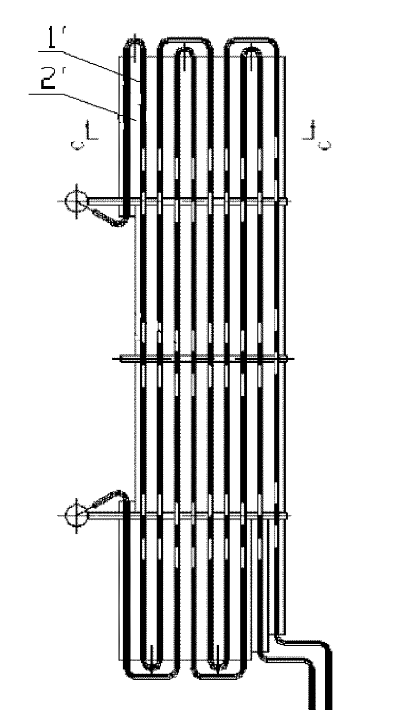
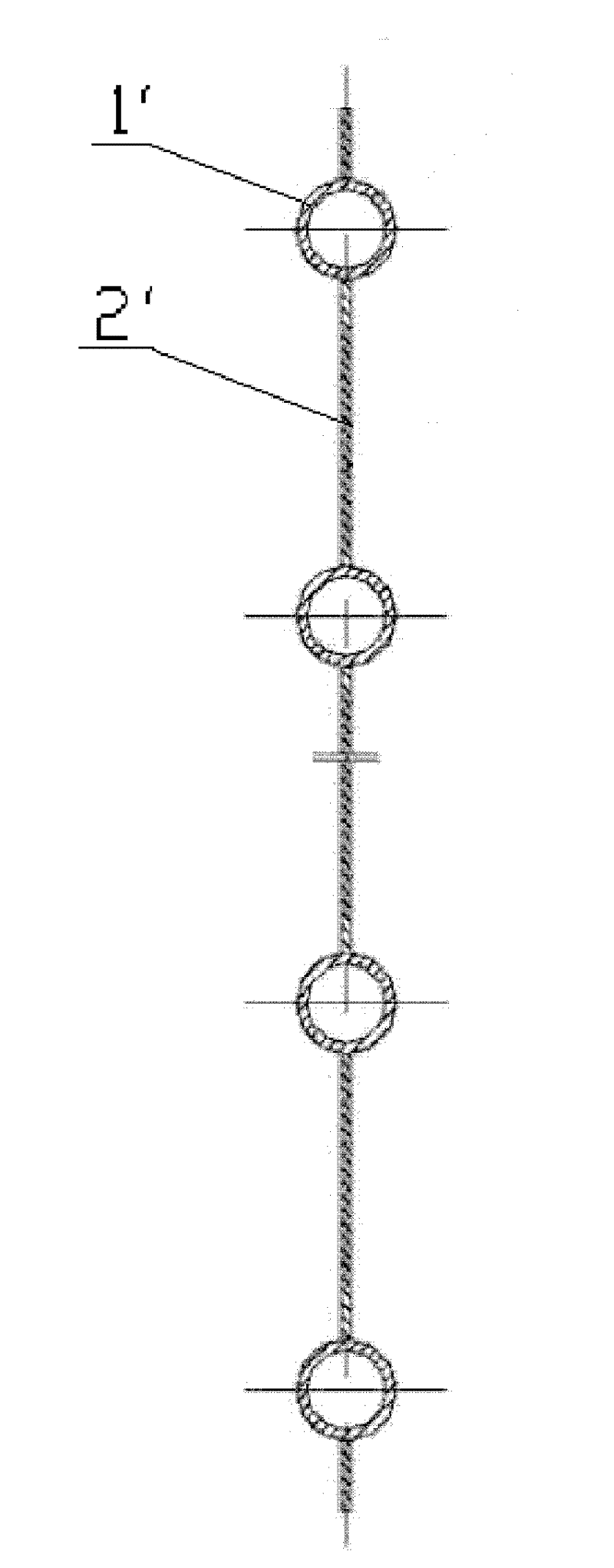
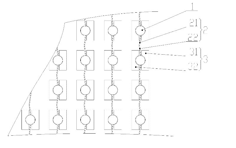
[0039] The core of the present invention is to provide a heat exchange tube whose structural design can effectively increase the heat exchange area of ​​the heat exchange tube without increasing or greatly increasing its occupied space, thereby significantly improving The heat transfer efficiency of the heat exchange tube. In addition, another core of the present invention is to provide a flue gas heat exchanger including the heat exchange tube.

[0040] In order to enable those skilled in the art to better understand the technical solutions of the present invention, the present invention will be further described in detail below in conjunction with the accompanying drawings and specific embodiments.

[0041] Please refer to image 3 , Figure 4 , Figure 5 and Figure 6 , image 3 It is a structural schematic diagram of the heat exchange tube in the first embodiment of the present invention; Figure 4 It is a structural schematic diagram of a heat exchange tube section ...


PUM


Abstract

The invention discloses a heat exchange tube. The heat exchange tube comprises a snake-shaped tube which is bent to form a plurality of heat exchange tube sections (1); axial heat exchange fins (2) are connected with both sides of each of the heat exchange tube sections (1) respectively along the axial direction; a plurality of radial heat exchange fins (3) are connected with the heat exchange tube sections (1); and each of the radial heat exchange fins (3) comprises a first heat exchange fin section (31) and a second heat exchange fin section (32) which are connected with both sides of the corresponding heat exchange tube section (1) along the radial direction and clamp the corresponding radial heat exchange fin (2) in a gap between the first heat exchange fin section (31) and the secondheat exchange fin section (32). Due to the structural design of the heat exchange tube, the heat exchange area of the heat exchange tube can be increased effectively on the basis of not increasing ornot increasing the occupied area in a large scale, so that the heat exchange efficiency of the heat exchange tube can be improved obviously. The invention also discloses a smoke heat exchanger comprising the heat exchange tube.

Description

technical field [0001] The invention relates to the technical field of flue gas heat exchange, in particular to a heat exchange tube. In addition, the present invention also relates to a flue gas heat exchanger comprising the heat exchange tube. Background technique [0002] With the depletion of non-renewable energy such as coal, oil and natural gas, more and more attention has been paid to energy recovery or recycling technology. Therefore, in the field of coal-fired boiler technology, flue gas heat exchange technology has been widely used. application. [0003] The prior art with the patent number "201020301096.2" discloses a heat exchange tube used in flue gas heat exchange technology. Specifically, please refer to figure 1 and figure 2 , figure 1 It is a structural schematic diagram of a heat exchange tube in the prior art, figure 2 for figure 1 The cross-sectional view of the CC direction. [0004] Such as figure 1 As shown, the heat exchange tube in the pri...

Claims


Application Information

Patent Timeline
Patent Type & Authority Patents(China)
IPC IPC(8): F28F1/08F28F1/14F28D1/06F23J15/00
Inventor 廖增安陈磊钟志良黄举福
Owner FUJIAN LONGKING
Why Eureka
Try Eureka