Transmission

A technology of transmission and synchronizer, which is applied in the direction of gear transmission, belt/chain/gear, mechanical equipment, etc. It can solve the problems of increasing the cost of the automatic transmission operating system, power interruption, and shortening the life of the clutch.

Inactive Publication Date: 2011-09-21
胡少旺
View PDF6 Cites 3 Cited by
  • Summary
  • Abstract
  • Description
  • Claims
  • Application Information

AI Technical Summary

Problems solved by technology

[0002] In the traditional automatic transmission system, when shifting gears, the clutch must be disengaged first, and then the transmission should be replaced with the corresponding gear, and then the clutch should be combined. In this way, the power will be reduced and the smoothness will be poor during the shifting process.
However, although the dual clutch saves the time for shifting gears of the gearbox when shifting gears, it still needs to completely separate the clutch of one gear and then combine the clutch of another gear. This will still cause the problem of power interruption. People often use One clutch is not completely disengaged, and the other clutch starts to combine to achieve uninterrupted power output, but the result of this will make the shifting operation very complicated, increase the cost of the automatic transmission operating system and reduce the life of the clutch. Moreover, there is still a short-term power decline during the shifting process. When the load is heavy and the slope is large, it will cause the vehicle to fail to drive normally, stall, slip and other accidents. This is something that the current transmission cannot do.

Method used


Image

  • Transmission
  • Transmission

Examples


Embodiment Construction

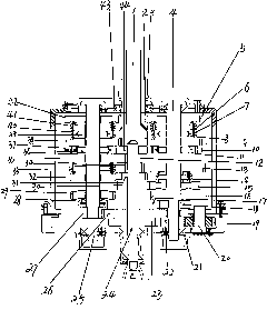
[0009] refer to figure 1 , the outer shaft 2 is fixed by the bearing 43 and extends out of the housing 3, the inner shaft 1 is fixed by the bearing and extends out of the outer shaft 2, the outer shaft 2 is connected with the protruding part of the inner shaft 1, and the groove end of the inner shaft 1 It is connected with the protruding ends of the inner two shafts 24, and the rear ends of the inner two shafts 24 are connected and fixed with the housing 3 through bearings. One-way clutch 36,39 is housed on, and brake 37 is housed outside one-way clutch 36, and synchronizer 40 is housed outside one-way clutch 39, and one, three, five and seven gear driving wheels 27,29,32,35 are also housed on the odd shaft 25 , Constant meshing gears 38,42, synchronizers 28,33,41. One-way clutch 8,11 is housed on the even shaft 4, and brake 10 is housed outside the one-way clutch 11, and synchronizer 7 is housed outside the one-way clutch 8, and reverse gear, second, forty-six gear driving w...


PUM


Abstract

The invention relates to an automatic transmission capable of outputting power as far as possible in a gear shift process. The front end of an outer shaft I provided by the invention is connected and fixed with a shell; the rear end of the outer shaft I is connected with the front end of a protrusion of an inner shaft I; the rear end of the inner shaft I is connected with the front end of a shaft II; an odd shaft and an even shaft are respectively installed in the shell and are positioned at the two sides of the shaft II; the odd shaft and the even shaft are all provided with two unidirectional clutches; a unidirectional clutch is externally provided with a band-type brake, and the other unidirectional clutch is externally provided with a constant mesh gear; the unidirectional clutches on the odd shaft and the even shaft are externally and respectively provided with a constant mesh gear which is meshed with the gear of an inner shaft I; and the unidirectional clutch which is externally provided with the constant mesh gear on the odd shaft or the even shaft is internally provided with a synchronizer between the odd shaft and the even shaft. According to the invention, in the process of gear shift by combining with the clutches, the original gear still works, the transmission outputs power as far as possible in the gear shift process, when an automobile slides backwards after start and stop in ascent, the automobile is locked automatically without the match of a brake.

Description

technical field [0001] The invention belongs to an automatic transmission in a vehicle, in particular to an automatic transmission that outputs 100% of the power of the transmission during the shifting process. Background technique [0002] In the traditional automatic transmission system, when shifting gears, the clutch must be disengaged first, then the transmission must be replaced with the corresponding gear, and then the clutch should be combined. In this way, the power will be reduced and the smoothness will be poor during the shifting process. However, although the dual clutch saves the time for shifting gears of the gearbox when shifting gears, it still needs to completely separate the clutch of one gear and then combine the clutch of another gear. This will still cause power interruption problems. People often use One clutch is not fully disengaged, and the other clutch starts to combine to achieve uninterrupted power output, but the result of this will make the shi...

Claims


Application Information

Patent Timeline
Patent Type & Authority Applications(China)
IPC IPC(8): F16H3/10
Inventor 胡少旺
Owner 胡少旺
Why Eureka
Try Eureka