
Light source module and lamp

A technology of light source modules and lamps, which is applied in the direction of light sources, electric light sources, point light sources, etc., and can solve problems such as yellow halo of lighting lamps

Inactive Publication Date: 2011-09-21
EVERLIGHT ELECTRONICS
View PDF8 Cites 6 Cited by
  • Summary
  • Abstract
  • Description
  • Claims
  • Application Information

AI Technical Summary

Problems solved by technology

In this way, it will cause yellow halo at the edge of the illumination range of the lighting fixture
[0004] In addition, generally, the wires of the existing LED lamps are routed from both ends of the lamps. Such a routing design will prevent multiple lamps from being arranged in a straight line in a close proximity along the direction of their extension.

Method used


Image

  • Light source module and lamp
  • Light source module and lamp
  • Light source module and lamp

Examples


Embodiment Construction

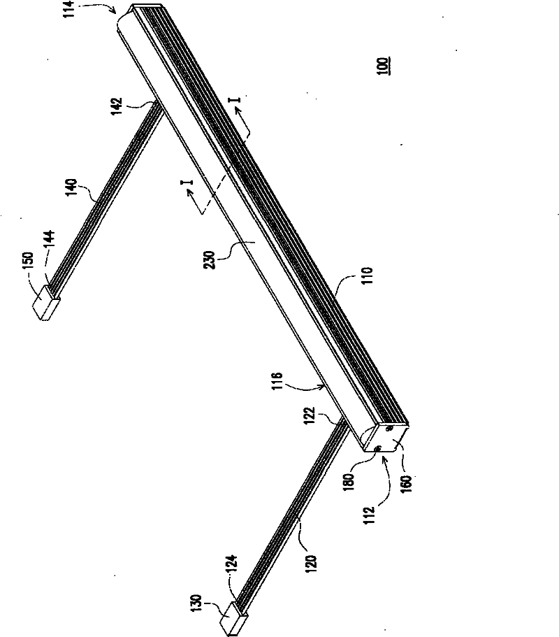
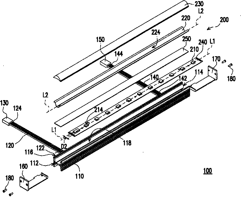
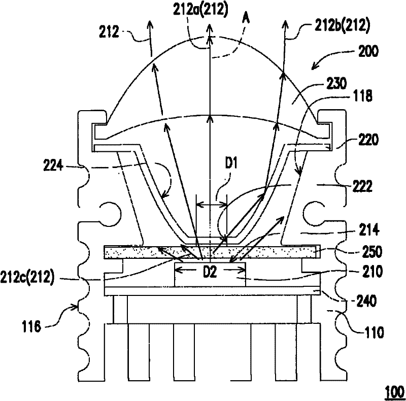
[0041] Figure 1A It is a perspective view of a lamp according to an embodiment of the present invention, Figure 1B for Figure 1A Exploded diagram of the luminaire, Figure 2A for Figure 1A The sectional view of the luminaire along the I-I line, while Figure 2B for Figure 1B Perspective view of the shading element in . Please refer to Figure 1A , Figure 1B , Figure 2A and Figure 2B , the lamp 100 of this embodiment includes a light source module 200 and a lamp holder 110 . The light source module 200 includes at least one light emitting element 210 (a plurality of light emitting elements 210 are taken as an example in the figure), a light shielding element 220 and a light guiding element 230 . The light emitting element 210 is adapted to emit a light beam 212 (such as Figure 2A shown). In this embodiment, the light emitting element 210 has an optical axis A. As shown in FIG. In addition, in this embodiment, the light emitting element 210 is, for example, a l...


PUM


Abstract

The invention relates to a light source module and a lamp, wherein the light source module comprises at least one light-emitting component, a light-shielding component and a light-guiding component. The light-emitting component is suitable for emitting a light beam; the light-shielding component is arranged between the light-guiding component and the light-emitting component and provided with at least one light-transmitting hole and at least one spotlighting reflection side; and a clearance is arranged between the light-shielding component and the light-emitting component; a first part of the light beam passes through the light-transmitting hole to be transmitted to the light-guiding component and then penetrates through the light-guiding component; a second part of the light beam passes through the light-transmitting hole to be reflected and accumulated by the spotlighting reflection side and then penetrates through the light-guiding component; and a third part of the light beam is unable to be transmitted to the light-guiding component because of the shading of the light-shielding component. The invention also discloses a lamp employing the light source module. The light source module provided in the invention has a smaller light-emitting angle; and the lamp provided in the invention also has a smaller light-emitting angle.

Description

technical field [0001] The invention relates to a light source module and a lamp. Background technique [0002] With the advancement of semiconductor technology, the power that can be achieved by a light-emitting diode (light-emitting diode, referred to as: LED) is getting higher and higher, and the intensity of the emitted light is getting higher and higher. In addition, light-emitting diodes have the advantages of power saving, long service life, environmental protection, fast start-up, and small size. Therefore, light-emitting diodes are also widely used in lighting equipment, traffic signs, monitors, optical mice and other products, and there is a tendency to gradually replace traditional fluorescent tubes. [0003] For existing small white light emitting diode lighting fixtures, there are generally the following two problems. First of all, the optical design space of small lamps is limited, and it is difficult to deflect the light with a large deflection angle emitted...

Claims


Application Information

Patent Timeline
Patent Type & Authority Applications(China)
IPC IPC(8): F21S2/00F21V8/00F21V7/10F21V11/00F21V13/00F21Y101/02F21K9/20F21Y115/10
Inventor 裴建昌董朝宪陈奕宏
Owner EVERLIGHT ELECTRONICS
Learn More