Brightness enhancement film and backlight module

A light-enhancing sheet, axisymmetric technology, applied to lighting devices, components of lighting devices, refractors, etc., can solve the problems of reduced light efficiency, increased cost, increased thickness of backlight module 40, etc., to achieve uniform brightness and good shading characteristics, the effect of good light-gathering characteristics

Inactive Publication Date: 2010-11-24
CORETRONIC
View PDF0 Cites 4 Cited by
  • Summary
  • Abstract
  • Description
  • Claims
  • Application Information

AI Technical Summary

Problems solved by technology

[0005] When the upper diffusion sheet 70b and the lower diffusion sheet 70a are not configured in the backlight module 40, since the surface of the prism column 84 is made of a plane, it is impossible to cover the diffusion dots 68 or defects on the light guide plate 60, and it is also impossible to make the diffusion dots 68 is blurred, so that the user will feel that the surface light source provided by the backlight module 40 is not uniform
Furthermore, since the outline of the prism column 84 (i.e. the ridge line L1 at the top and the boundary line L2 between two adjacent prism columns 84) is obvious, this will make the prism column 84 and the liquid crystal panel (liquid) disposed above the backlight module 40 The pixel array (not shown) of a crystal panel (LCD) forms a moiré pattern or a Newton ring (Newton ring), which leads to uneven display images provided by the LCD panel
[0006] However, if the upper diffuser 70b and the lower diffuser 70a are added in order to improve the above problems, the cost will increase and the light loss will increase, and the thickness of the backlight module 40 will be increased.
In addition, the sharp ridge line L1 of the prism column 84 is also likely to cause scratches between the prism sheet 80 and the adjacent film material (such as the upper diffusion sheet 70b)
In addition, the mechanism of multiple cycles of the light beam 92 will increase the amount of the light beam 92 absorbed by the reflective sheet 50, the light guide plate 60, the lower diffusion sheet 70a, the prism sheet 80, or the upper diffusion sheet 70b, resulting in an increase in the light loss of the backlight module 40, Reduced light efficiency

Method used


Image

  • Brightness enhancement film and backlight module
  • Brightness enhancement film and backlight module
  • Brightness enhancement film and backlight module

Examples


Embodiment Construction

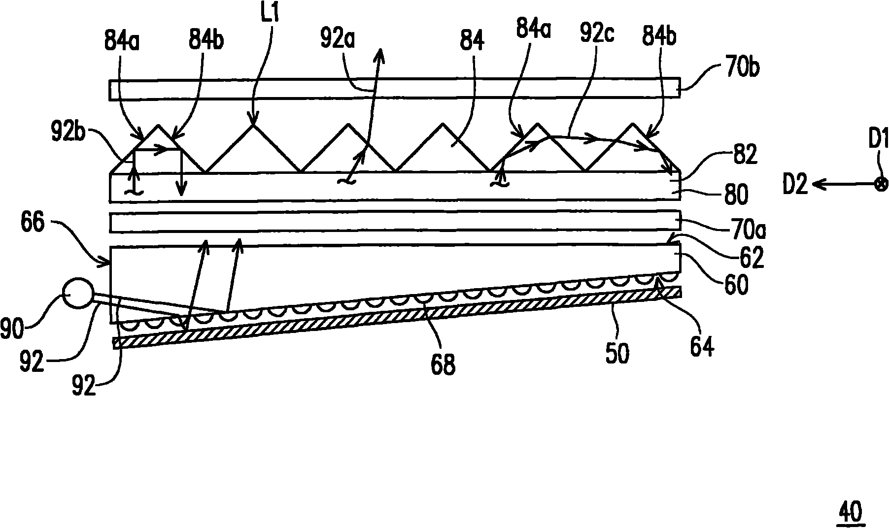
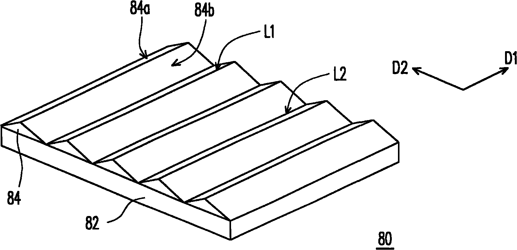
[0071] The description of the following embodiments refers to the attached drawings to illustrate specific embodiments that the present invention can be implemented. The terms of the direction mentioned in the present invention, such as "up", "down", "front", "rear", "left", "right", etc., are only directions for referring to the attached drawings. Therefore, the directional terms used are used to illustrate rather than to limit the present invention.

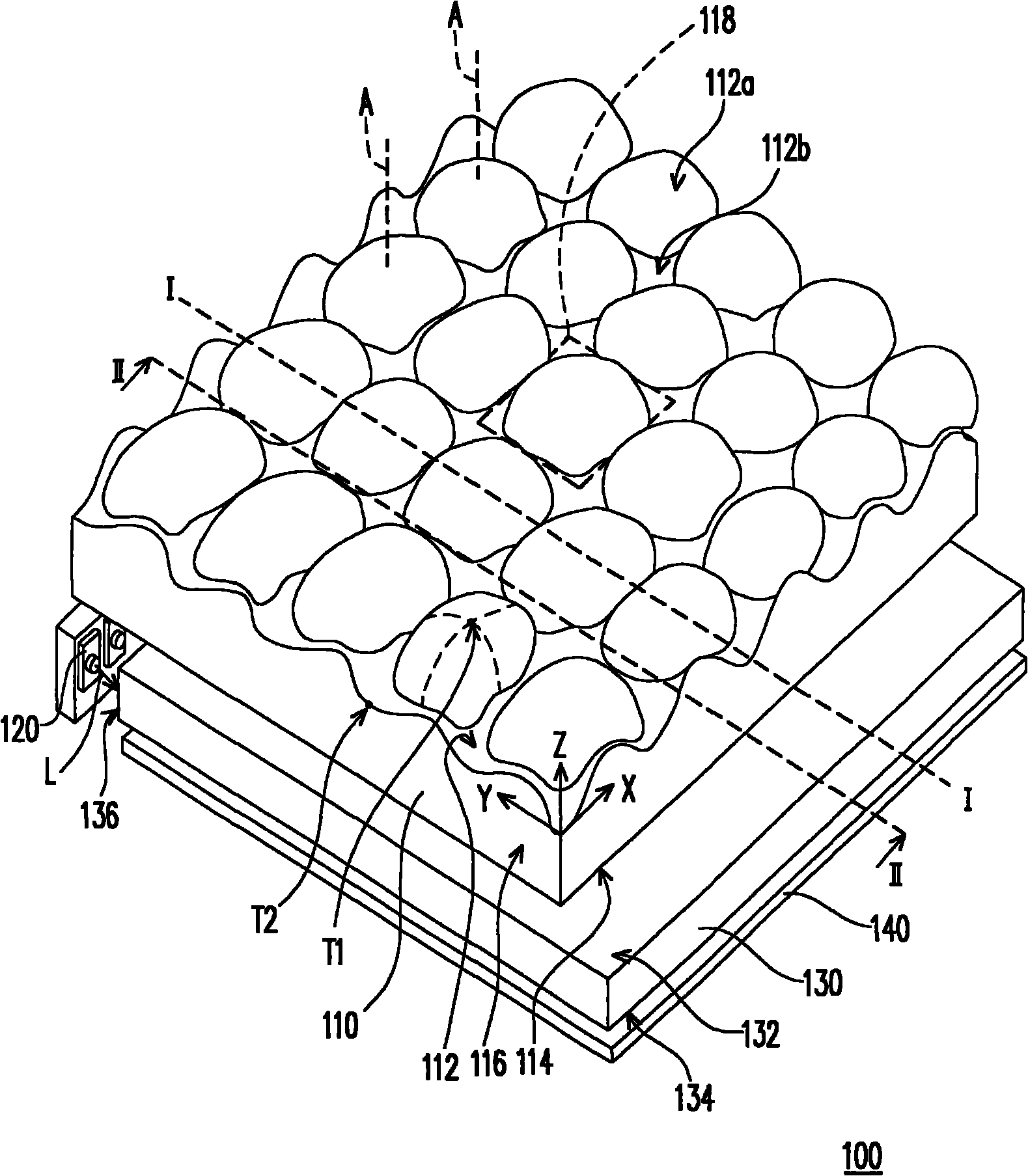
[0072] In this specification, an object that is axisymmetric means that a symmetry axis can be found and after the object is rotated around the symmetry axis at any angle, the shape of the object can be substantially the same as the shape before the rotation. In addition, if an object is non-axisymmetric, it is defined as that no axis of symmetry can be found so that after the object is rotated at any angle around the axis of symmetry, the shape of the object can be substantially the same as the shape before the rotation.

[0073] ...


PUM


Abstract

The invention relates to a brightness enhancement film, which comprises a first surface, a second surface and a side face. The first surface is a curved surface which continuously fluctuates on two dimensions and comprises a plurality of axisymmetrical convex surfaces and a plurality of non-axisymmetrical concave surfaces, and each axisymmetrical convex surface is a curved surface; the axisymmetrical convex surfaces and the non-axisymmetrical concave surfaces are alternately arrayed on the two dimensions to form a plurality of wave crests and a plurality of wave troughs respectively, and each non-axisymmetrical concave surface is a curved surface; the second surface corresponds to the first surface; and the side face is connected with the first surface and the second surface. The invention also provides a backlight module using the brightness enhancement film.

Description

【Technical Field】 [0001] The present invention relates to an optical film and a light source module, and particularly relates to a brightness enhancement film (BEF) and a backlight module. 【Background technique】 [0002] Figure 1A Is a cross-sectional view of a conventional backlight module, Figure 1B for Figure 1A A perspective view of the prism sheet. Please refer to Figure 1A and Figure 1B , The conventional backlight module 40 includes a reflective sheet 50, a light guide plate 60, a bottom diffuser 70a, a prism sheet 80 and an upper diffuser which are sequentially arranged from the back side to the front side. (top diffuser)70b. The light guide plate 60 has a first surface 62, a second surface 64 opposite to the first surface 62, and a light incident surface 66 connecting the first surface 62 and the second surface 64. A cold cathode fluorescent lamp (CCFL) 90 is arranged on one side of the light incident surface 66. The cold cathode fluorescent tube 90 is adapted to em...

Claims


Application Information

Patent Timeline
Patent Type & Authority Applications(China)
IPC IPC(8): F21V5/00
Inventor 邓敦建臧志仁曾能荣
Owner CORETRONIC
Why Eureka
Try Eureka