Heat-dissipation structure for LED (Light Emitting Diode) light

A technology of LED lamps and heat dissipation structures, which is applied to lighting and heating equipment, cooling/heating devices of lighting devices, lighting devices, etc., can solve the problems of high junction temperature, insufficient service life, and low luminous efficiency of LED lamps. , to achieve the effect of improving reliability and service life

Inactive Publication Date: 2011-09-21
CELESTICA TECH CONSULTANCY SHANGHAI
View PDF3 Cites 8 Cited by
  • Summary
  • Abstract
  • Description
  • Claims
  • Application Information

AI Technical Summary

Problems solved by technology

[0005] Disadvantages of indoor LED lamps that use radiators to dissipate heat: LED lamp

Method used


Image

  • Heat-dissipation structure for LED (Light Emitting Diode) light
  • Heat-dissipation structure for LED (Light Emitting Diode) light
  • Heat-dissipation structure for LED (Light Emitting Diode) light

Examples


Embodiment 1

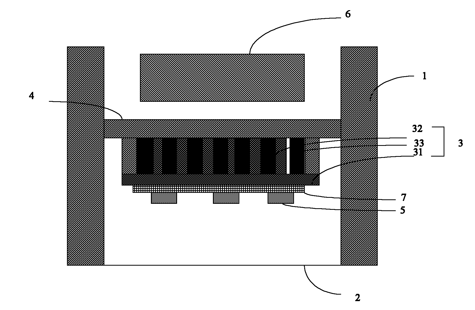
[0018] see figure 2 The heat dissipation structure of an LED lamp is shown, which includes a cavity surrounded by an LED lamp housing 1 and a lens 2 and a driving power source 6 accommodated in the cavity; the cavity is provided with an energy storage cavity 3, The housing bottom plate 4 forming a sealed cavity with the energy storage cavity, the PCB board 7 connected with the energy storage cavity 3 and the LED particles 5 on the PCB board 7 . The energy storage cavity 3 cooperates with the housing bottom plate 4 to form several sealed cavities, and the sealed cavities are used to fill the phase change material 33 to form a phase change material layer.

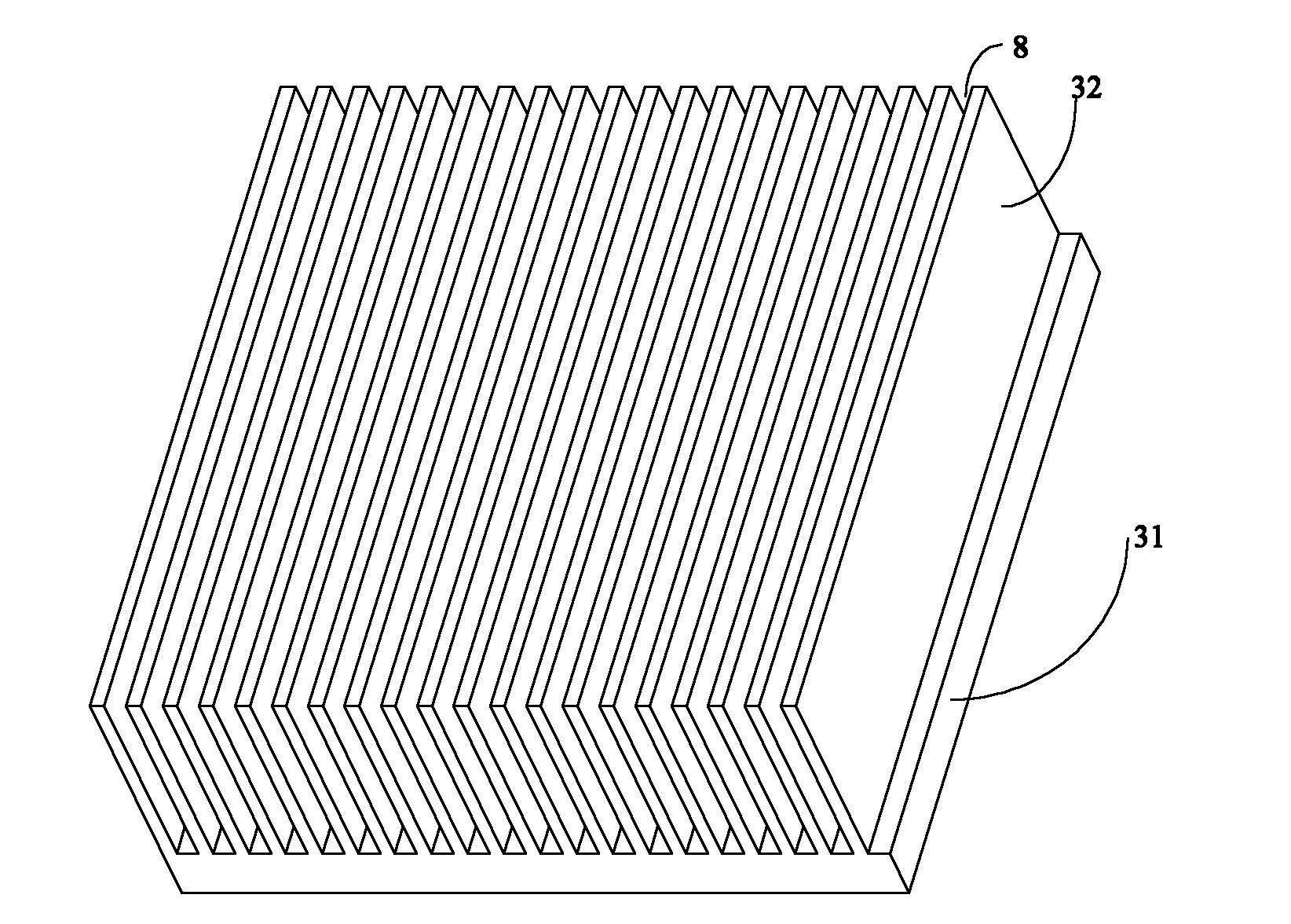
[0019] Please continue to refer to image 3 As shown, the energy storage cavity 3 includes a substrate 31 , a fin array 32 located on the substrate 31 , and a phase change material layer 33 accommodated in the fin array 32 . The fin array 32 and the casing bottom plate 4 form a sealed cavity for accommodating the phase cha...

Embodiment 2

[0023] see Figure 4 As shown, the energy storage cavity can also be Figure 4 In the structure shown, the energy storage cavity includes a substrate 31 ′, a fin array 32 ′ located on the substrate 31 ′, and a phase change material layer 33 ′ accommodated in the fin array 32 ′. The fin array 32 ′ and the bottom plate of the casing form a sealed cavity for accommodating the phase change material layer. The fin array 32 ′ is perpendicular to the base plate 31 ′, and is roughly a plurality of spaced cylinders, and spaced slots are formed between the cylinders. The bottom plate of the housing also includes the bottom plate and the sides perpendicular to the bottom plate and distributed around the bottom plate. Wall; the housing bottom plate surrounds the fin array 32', thereby forming several sealed cavities. The material of the energy storage cavity is mainly metal, such as aluminum and the like.

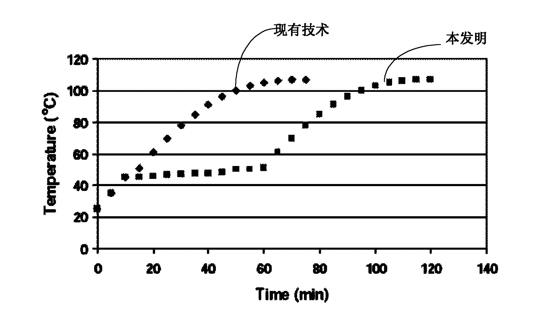
[0024] The principle of the present invention is: the service time of the indoo...


PUM

PropertyMeasurementUnit
Thermal conductivityaaaaaaaaaa

Abstract

The invention provides a heat-dissipation structure for an LED (Light Emitting Diode) light. The heat-dissipation structure comprises a cavity defined by an LED light shell (1) and a lens (2), and a driving power supply (6) accommodated in the cavity. The heat-dissipation structure is characterized in that the an energy accumulation cavity (3), a shell baseplate (4), a PCB (Printed Circuit Board) (7) and LED granules (5) are arranged in the cavity, wherein the shell baseplate (4) and the energy accumulation cavity are matched to form a sealed cavity, the PCB (7) is connected with the energy accumulation cavity (3), and the LED granules (5) are arranged on the PCB (7). According to the invention, phase-change materials with a certain mass is embedded in the energy accumulation cavity; when the LED light works, heat generated by the LED granules is transferred to the PCB and then transferred to the phase-change material layer through the baseplate of the energy accumulation cavity; when heated to fusing point temperature, the phase-change material begins to absorb a great quantity of heat generated by the LED granules to keep the temperature of LEDs unchanged basically until the phase change process of all the phase-change materials is finished. By adopting the heat-dissipation structure, the reliability and the service life of the LED light can be improved.

Description

technical field [0001] The invention belongs to the field of heat dissipation of LED lamps, in particular to a heat dissipation structure of LED lamps. Background technique [0002] LED has long been used in instruments and computers as operating status indicators, mainly due to its high reliability and low power consumption. However, in recent years, LEDs have been used as lighting equipment, so the power consumption of LEDs has also increased rapidly, and the heat flux density of LED particles can even compete with CPUs. [0003] LED is a photoelectric device, only about 10%-40% of the electrical energy is converted into light energy during the working process, and the rest of the electrical energy is almost converted into heat energy, which increases the junction temperature of the LED. The rise of the junction temperature of the LED reduces the luminous efficiency of the LED lamp, deteriorates the reliability, and reduces the service life. Therefore, heat dissipation is...

Claims


Application Information

Patent Timeline
IPC IPC(8): F21V29/00F21Y101/02F21V29/74F21V29/85F21Y115/10
Inventor 范垚银
Owner CELESTICA TECH CONSULTANCY SHANGHAI
Why Eureka
Try Eureka