Automatic speed adjusting device for small-size two-stroke gasoline engine

A gasoline engine, automatic speed regulation technology, applied in the direction of engine control, machine/engine, mechanical equipment, etc., can solve problems such as product launch, and achieve the effect of increasing reliability and service life

Inactive Publication Date: 2015-07-22
ZHEJIANG ZHONGJIAN TECH
7 Cites 2 Cited by

AI-Extracted Technical Summary

Problems solved by technology

For this reason, many manufacturers, scientific research institutes and people of insi...

Abstract

The invention discloses an automatic speed adjusting device for a small-size two-stroke gasoline engine. The device comprises a carburetor (1), an adjustable-speed motor (3), a circuit controller (4), the engine (5), a flywheel and magnet motor (6) and an engine high pressure pack (7), the adjustable-speed motor (3) is fixed on the carburetor (1) through a mounting bracket (2), engine speed signals of the flywheel and magnet motor (6) which is installed on a crankshaft of the engine (5) are transmitted to the circuit controller (4), after making comparison with a set revolving speed, the circuit controller (4) outputs an adjustable-speed motor revolution signal, the adjustable-speed motor (3) is made to revolve forward or reversely, the accelerator opening of the carburetor (1) is driven by the adjustable-speed motor (3) to be opened or closed for a certain angle, the accelerator opening variation of the carburetor (1) controls the revolving speed of the engine (5), and the engine (5) is made to work at a constant speed under the set revolving speed. By means of the structure, the device has the advantages that the structure is simple and reasonable, the operation and use are convenient, the engine speed is adjusted automatically according to the set revolving speed, the operation is safe and reliable, and the device is capable of meeting emission requirements of the United States and the European Union.

Application Domain

Fuel-injection pumpsMachines/engines

Technology Topic

FlywheelMagnet +8

Image

  • Automatic speed adjusting device for small-size two-stroke gasoline engine
  • Automatic speed adjusting device for small-size two-stroke gasoline engine
  • Automatic speed adjusting device for small-size two-stroke gasoline engine

Examples

  • Experimental program(1)

Example Embodiment

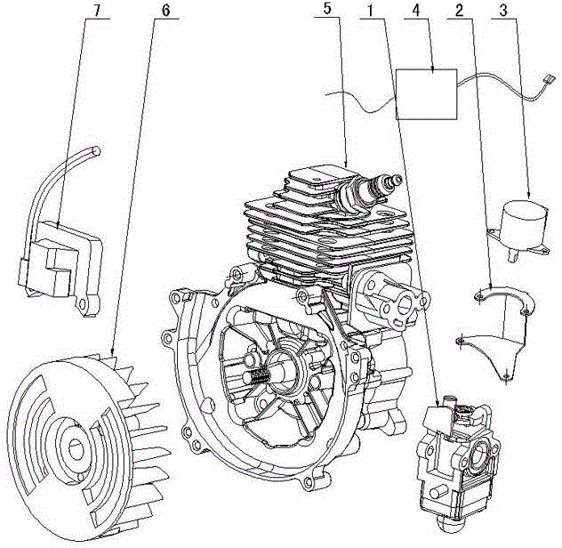
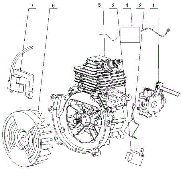
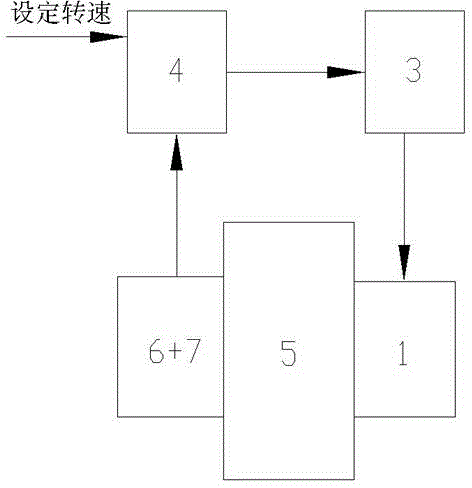
[0015] Figure 1 to Figure 3 Shown, for the present invention creates the concrete embodiment of a kind of small two-stroke gasoline engine automatic speed control device, it comprises carburetor 1, speed regulating motor 3, circuit controller 4, engine 5, flywheel and magneto 6, engine High voltage pack 7, speed regulating motor 3 are fixed on the carburetor 1 by mounting bracket 2, and the engine speed signal of the flywheel and magneto 6 that are installed on the crankshaft of engine 5 is transmitted to circuit controller 4, and circuit controller 4 and After the set speed is compared, the rotation signal of the speed regulating motor is output, so that the speed regulating motor 3 rotates forward or reversely, the throttle opening of carburetor 1 is opened or closed at a certain angle driven by speed regulating motor 3, and the throttle opening of carburetor 1 changes Control the engine 5 rotating speed, make the engine 5 rotating speed work at a constant speed under the set rotating speed. The circuit controller 4 is connected between the engine high voltage pack 7 and the speed regulating motor 3 , and the working power of the circuit controller 4 is provided by the engine high voltage pack 7 .
[0016] When the carburetor 1 adopts a rotary valve carburetor, the rotating shaft of the speed regulating motor 3 is connected with the rotary valve shaft of the rotary valve carburetor, and the rotating shaft rotation direction of the speed regulating motor 3 is the same as that of the rotary valve. The rotary valve shaft of the type carburetor rotates in the same direction.
[0017] When the carburetor 1 adopts a butterfly valve carburetor, the rotating shaft of the speed regulating motor 3 is connected with the throttle shaft of the butterfly valve carburetor, and the rotating shaft of the speed regulating motor 3 is in the same direction as the butterfly valve carburetor. The direction of rotation of the throttle valve of the controller is the same.
[0018] The embodiment of the present invention is as follows, first set the rotating speed for the circuit controller 4, then start the engine 5, and make it run at idle speed. During normal work, turn on the switch to make the speed regulating motor 3 run, open the carburetor 1 damper to make the engine 5 run at high speed. The flywheel and the magneto 6 installed on the crankshaft of the engine 5 make the engine high-voltage package 7 ignite once every one week of operation, and transmit the engine speed signal to the circuit controller 4 to compare with the set speed. After the circuit controller 4 judges, the speed is too low or when it is too high, the circuit controller 4 sends the speed regulating motor rotation signal to control the speed regulating motor 3, so that the speed regulating motor 3 rotates a certain angle clockwise or counterclockwise, and the throttle opening of the carburetor 1 is driven by the speed regulating motor 3 to open Or off at an angle. When the throttle of the carburetor 1 is opened, the intake air volume of the mixture increases, and the speed of the engine 5 increases; when the throttle of the carburetor 1 is closed, the intake air volume of the mixture decreases, and the speed of the engine 5 decreases. During the whole working process, the circuit controller 4 monitors the rotation speed of the engine 1 in real time, and feeds back in time to automatically control the engine 5 to work at a constant speed at a set rotation speed.
[0019] The above is only an embodiment of the invention, and does not impose any formal restrictions on the invention. On the basis of not departing from the technical solution of the invention, any simple modification, equivalent change or modification shall fall into the The scope of protection created by the present invention.

PUM

no PUM

Description & Claims & Application Information

We can also present the details of the Description, Claims and Application information to help users get a comprehensive understanding of the technical details of the patent, such as background art, summary of invention, brief description of drawings, description of embodiments, and other original content. On the other hand, users can also determine the specific scope of protection of the technology through the list of claims; as well as understand the changes in the life cycle of the technology with the presentation of the patent timeline. Login to view more.

Similar technology patents

Friction braking device

PendingCN108248631Areduce weightImprove reliability and service life
Owner:BEIJING TIANYOUXINPEI HIGH TECH CO LTD

Three-leg inverter-driven motor system, phase sequence detection method and device of motor system

InactiveCN106887993AImprove reliability and service lifeRealize frequency conversion speed regulation
Owner:GUANGZHOU BEDFORD ELECTRIC EQUIP

Assurance method of insulation distance of high-voltage coil

PendingCN107808762AReduce arcing and breakdownImprove reliability and service life
Owner:TIANJIN HUIGAO MAGNETICS

Clutch device for retarder, vehicle including such a clutch device and method for engaging a retarder

InactiveCN104955687AReduce startup timeImprove reliability and service life
Owner:SCANIA CV AB

Electrochemical device and electronic apparatus

PendingCN114270622AImprove connection reliabilityImprove reliability and service life
Owner:NINGDE AMPEREX TECH

Classification and recommendation of technical efficacy words

  • Improve reliability and service life

Method for determining amount of wear, method for manufacturing sliding contact, and sliding contact

InactiveCN102278966AImprove reliability and service lifeExtended service life
Owner:ROBERT BOSCH GMBH +1

Distributed driven type rocking sieve

ActiveCN103752498AImprove screening efficiencyImprove reliability and service life
Owner:CHINA UNIV OF MINING & TECH

Novel sea water desalinization evaporator

ActiveCN101780988Areduce vibration intensityImprove reliability and service life
Owner:CHINA FIRST HEAVY IND +1

Fiber jumper wire joint and large-power semiconductor laser assembly

InactiveCN104317009AImprove reliability and service lifeWide range of applications
Owner:WUHAN RUIZE TECH DEV +1

Movable sun visor mechanism for vehicle light type switch

ActiveCN105644421AImprove reliability and service lifeAvoid shading
Owner:HASCO VISION TECHNOLOGY CO LTD
Why Eureka
Try Eureka