
Signalling remote control circuit

A remote control circuit and signal machine technology, applied in signal transmission systems, instruments, etc., can solve the problems of high bit error rate and poor anti-interference ability, and achieve the effect of low bit error rate, stable performance and scientific design

Inactive Publication Date: 2013-03-06
SAMOST PHOTOELECTRICITY TECH
View PDF1 Cites 0 Cited by
  • Summary
  • Abstract
  • Description
  • Claims
  • Application Information

AI Technical Summary

Problems solved by technology

[0002] When the traffic police command the traffic at the intersection, in order to control the signal machine conveniently, a special remote control is needed to remotely control the signal machine so that the signal light can be released according to the command of the traffic police. However, most of the signal machine remote controls on the market currently use fixed-code remote controls. This kind of remote control has the disadvantages of poor anti-interference ability and high bit error rate.

Method used


Image

  • Signalling remote control circuit
  • Signalling remote control circuit
  • Signalling remote control circuit

Examples


Embodiment Construction

[0011] The technical solutions of the present invention will be described in further detail below through specific implementation methods.

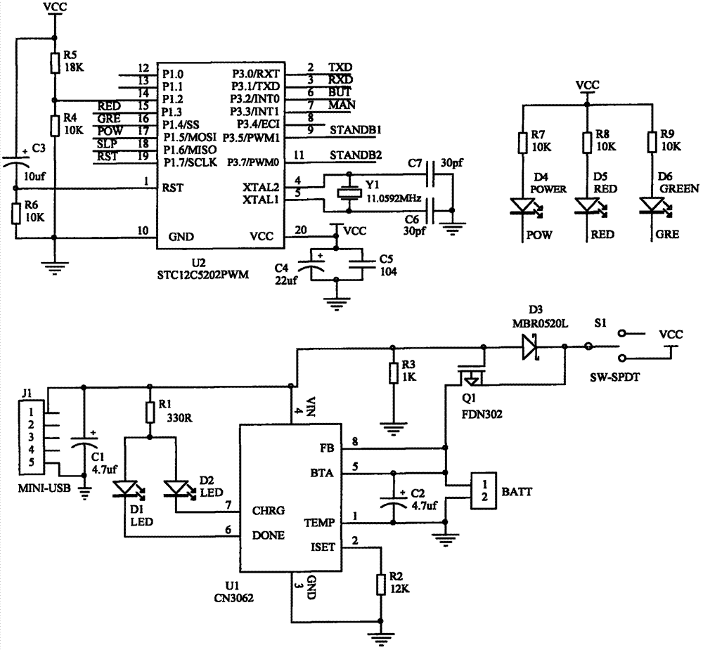
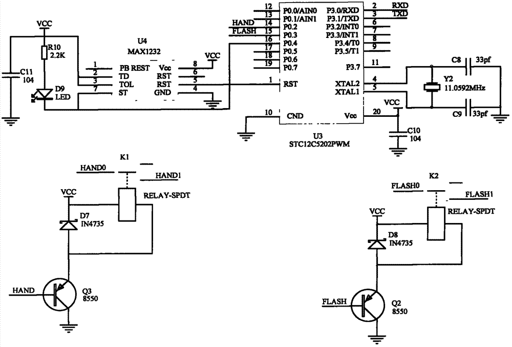
[0012] Such as figure 1 , figure 2 with image 3 As shown, a signal remote control circuit, which includes a hand-held terminal remote control circuit and a signal receiver circuit that communicate with each other;

[0013] The handheld terminal remote control circuit includes a microprocessor circuit 1, a key input circuit, a wireless communication module 1 and a power supply module, wherein the microprocessor circuit 1 is connected to the key input circuit so as to input remote control commands, and the microprocessor The circuit 1 is connected to the wireless communication module 1 so as to send remote control commands and receive signal machine status information sent by the wireless communication module 2. The power supply module is connected to the microprocessor circuit 1, the key input circuit and the wireless communication mod...


PUM


Abstract

Provided is a signalling remote control circuit, comprising a hand-held end remote control circuit and a signalling receiving end circuit in a mutual communication. The hand-held end remote control circuit comprises a microprocessor circuit 1, a button input circuit, a wireless communication module 1 and a power supply module, wherein the microprocessor circuit 1 is connected to the button input circuit, the microprocessor circuit 1 is connected to the wireless communication module 1, the power supply module is respectively connected to the microprocessor circuit 1, the button input circuit and the wireless communication module 1. The signalling receiving end circuit comprises a microprocessor circuit 2, a wireless communication module 2, a command execution circuit and a power supply circuit, wherein the microprocessor circuit 2 is connected to the command execution circuit and the power supply circuit is respectively connected to the microprocessor circuit 2, the command execution circuit and the wireless communication module 2. The circuit has advantages such as scientific design, convenient usage, strong anti-interference capability, low error rate, safety and reliability and stable performance.

Description

technical field [0001] The invention relates to a remote control circuit, in particular to a signal machine remote control circuit. Background technique [0002] When the traffic police direct the traffic at the intersection, in order to control the signal machine conveniently, a special remote control is needed to remotely control the signal machine so that the signal light can be released according to the command of the traffic police. However, most of the signal machine remote controls on the market currently use fixed-code remote controls. This kind of remote control has the disadvantages of poor anti-interference ability and high bit error rate. In order to solve this problem, people have been seeking an ideal technical solution. Contents of the invention [0003] Aiming at the deficiencies of the prior art, the present invention provides a signal machine remote control circuit with scientific design, convenient use, strong anti-interference ability, low bit error ra...

Claims


Application Information

Patent Timeline
Patent Type & Authority Patents(China)
IPC IPC(8): G08C17/02
Inventor 陈广合任小军余建华
Owner SAMOST PHOTOELECTRICITY TECH
Learn More