Method for detecting crosstalk between adjacent pixels of display panel

A technology for display panels and adjacent pixels, which is applied to static indicators, cathode ray tube indicators, instruments, etc., can solve the problem of detecting the degree of crosstalk between adjacent pixels, and achieve the effect of simple and easy detection methods.

Active Publication Date: 2011-09-21
BOE TECH GRP CO LTD
View PDF3 Cites 5 Cited by
  • Summary
  • Abstract
  • Description
  • Claims
  • Application Information

AI Technical Summary

Problems solved by technology

[0005] Crosstalk between adjacent pixels not only occurs in dual-view displays, but also in general displays. Therefore, in the process of producing displays, manufacturers need to screen out the crosstalk between adjacent pixels from multiple display panels. As small a display panel as possible, but there is currently no way to detect the degree of crosstalk between adjacent pixels

Method used


Image

  • Method for detecting crosstalk between adjacent pixels of display panel
  • Method for detecting crosstalk between adjacent pixels of display panel
  • Method for detecting crosstalk between adjacent pixels of display panel

Examples


Embodiment 1

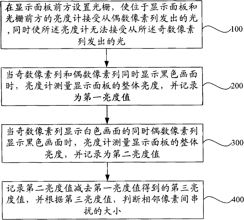
[0027] This embodiment provides a method for detecting crosstalk between adjacent pixels of a display panel, where the display panel includes odd-numbered pixel columns and even-numbered pixel columns arranged at intervals, figure 2 The flow chart of the method for detecting the degree of crosstalk between adjacent pixels of the display panel provided by Embodiment 1 of the present invention, from figure 2 As can be seen from , the detection method for crosstalk between adjacent pixels of the display panel includes:

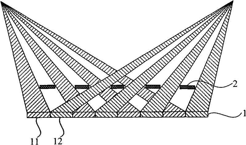
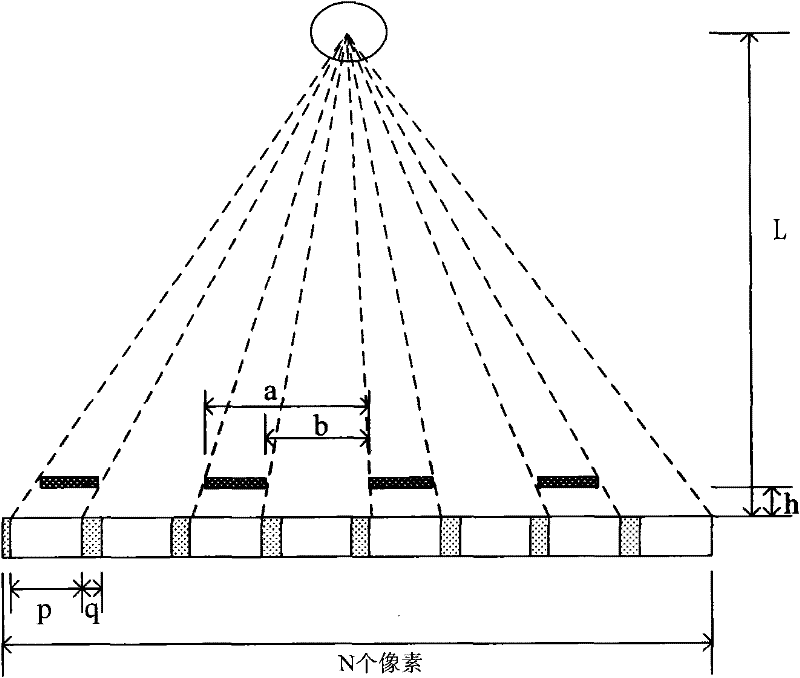
[0028] Step 100, setting a grating in front of the display panel, so that the luminance meter located in front of the display panel and the grating can receive the light emitted from the even-numbered pixel columns, while making the luminance meter unable to accept the light emitted from the odd-numbered pixel columns;

[0029] Step 200, when the odd-numbered pixel columns and the even-numbered pixel columns simultaneously display a black picture, the luminance...

Embodiment 2

[0038] This embodiment provides a method for detecting crosstalk between adjacent pixels of a display panel, where the display panel includes odd-numbered pixel columns arranged at intervals. Figure 4 The flow chart of the method for detecting crosstalk between adjacent pixels of a display panel provided in Embodiment 2 of the present invention, from Figure 4 As can be seen from , the detection method for crosstalk between adjacent pixels of the display panel includes:

[0039] Step 101, setting a grating in front of the display panel, so that the luminance meter located in front of the display panel and the grating can receive the light emitted from the even-numbered pixel columns, and at the same time make the luminance meter unable to accept the light emitted from the odd-numbered pixel columns;

[0040] Step 201, when the odd-numbered pixel columns and the even-numbered pixel columns display a white picture at the same time, the luminance meter measures the overall lumin...


PUM


Abstract

The invention relates to a method for detecting crosstalk between adjacent pixels of a display panel. The method comprises the following steps of: arranging an optical grating in front of the display panel, allowing a luminance meter to receive light emitted from even pixels and preventing the luminance meter from receiving the light emitted by odd pixels; measuring overall brightness of the display panel by the luminance meter and recording the overall brightness as a first brightness value when an odd pixel row and an even pixel row simultaneously display black pictures; measuring the overall brightness of the display panel by the luminance meter and recording the overall brightness as a second brightness value when the odd pixel row displays a white picture and the even pixel row displays a black picture at the same time; and recording a third brightness value obtained by subtracting the first brightness value from the second brightness value, and judging amplitude of the crosstalkbetween the adjacent pixels according to the third brightness value. According to the method, the amplitude of the crosstalk between the adjacent pixels of the display panel can be detected; and the detection method is simple and practical, has no need of complex instruments and the like.

Description

technical field [0001] The invention relates to display technology, in particular to a detection method for crosstalk between adjacent pixels of a display panel. Background technique [0002] The dual-view display technology is to set a grid in front of the display panel to realize the display of different images observed at different viewing positions. [0003] figure 1 It is a schematic diagram of the display technology of the dual-view display in the prior art, from figure 1 It can be seen from the figure that the dual-view display includes a display panel 1 and a grid 2 arranged in front of the display panel 1, and the above-mentioned display panel 1 includes odd pixel columns 11 and even pixel columns 12, and the grid 2 includes light blocking bars and slit, while the odd-numbered pixel columns 11 display the first image, and the even-numbered pixel columns 12 display the second image different from the first image, the first image gathers to the left viewing area aft...

Claims


Application Information

Patent Timeline
Patent Type & Authority Applications(China)
IPC IPC(8): G09G5/00
Inventor 武延兵
Owner BOE TECH GRP CO LTD
Why Eureka
Try Eureka