Packaged battery

A battery and casing technology, applied in the field of internal structure of the exterior casing, can solve problems such as core package damage, and achieve high safety performance

Inactive Publication Date: 2011-09-21
SANYO ELECTRIC CO LTD
View PDF4 Cites 3 Cited by
  • Summary
  • Abstract
  • Description
  • Claims
  • Application Information

AI Technical Summary

Problems solved by technology

[0009] Thus, in Figure 15 In the conventional packaged battery shown, the portion of the core pack that is in contact with the front ends of the ribs 926a, 926b is greatly damaged.

Method used


Image

  • Packaged battery
  • Packaged battery
  • Packaged battery

Examples


Embodiment approach

[0064] In the embodiment, taking the battery pack 1 for a notebook computer as an example, the structural features and the functions and effects thereof will be described.

[0065] 1. Appearance structure

[0066] use figure 1 , the appearance structure of the packaged battery 1 according to the embodiment will be described.

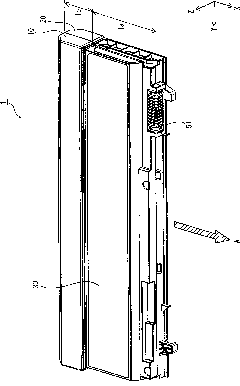
[0067] Such as figure 1 As shown, in the packaged battery 1 , the outer case is formed by combining the upper case member 10 and the lower case member 20 . In addition, a label 30 is attached to the top surface (outer bottom surface on the upper side in the Z-axis direction) of the upper case member 10 . On the label 30 , for example, precautions for use by the user, precautions for recycling, and the like are described.

[0068] The packaged battery 1 is inserted into the notebook computer in the direction of the arrow A (near side in the X-axis direction), and a part 1a thereof is accommodated in the notebook computer, while the remaining part 1b...

Deformed example 1

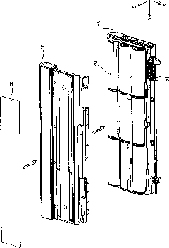
[0101] use Figure 9 The packaged battery 2 of Modification 1 will be described. It should be noted that only differences from the packaged battery 1 of the above-mentioned embodiment will be described below, and the other configurations have the same structure as the packaged battery 1 of the above-mentioned embodiment.

[0102] Such as Figure 9 As shown, in the packaged battery 2 of this modified example, the inner wall 126 of the lower case member 120 has a corner portion as a starting point and has a space (indicated by an arrow G) between the cells 49 and the like of the core pack. ) of the separated part, and also has a surface contact portion 126b that is in surface contact with the lead plate 55 of the core package, and this structure is the same as above.

[0103] However, in the lower case member 120 of the packaged battery 2 of the present modified example, the separated portion is parallel to the extending direction (X-axis direction) of the corresponding outer ...

Deformed example 2

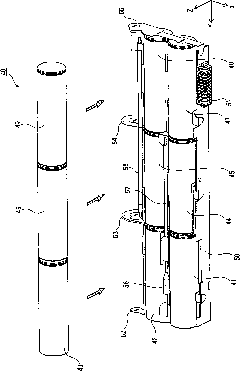
[0106] use Figure 10 and Figure 11 , the structure of the packaged battery of Modification 2 will be described. It should be noted that only differences from the packaged battery 1 of the above-mentioned embodiment will be described below, and the other configurations have the same structure as the packaged battery 1 of the above-mentioned embodiment.

[0107] First, if Figure 10 As shown, a plurality of slits 221 a are formed on the outer side wall 221 of the lower housing member 220 . The slits 221a are provided corresponding to the positions where the holes 225a are opened in the inner walls 225 arranged in parallel. Specifically, in this modified example, the slits 221a are provided to correspond to the three holes 225a of the inner wall 225, and cover a region wider than them in the Y-axis direction. Such as Figure 10 As shown in the part surrounded by double-dashed lines, with regard to the size of the slit 221a, the height H from the edge of the opening of the ...


PUM


Abstract

The invention provides a packaged battery which is capable of protecting a core pack accommodated therein from being damaged easily even in a case of application of a force to an outer packaging housing thereof from the outside and consequently has high safety performance. The packaged battery comprises an outer packaging housing formed by oppositely combining the mutual opening portions of an upper housing member (10) and a lower housing member (20) with each other. A core pack including a plurality of individual batteries (49...) are received in the outer packaging housing. Besides, an inner wall (26) is arranged inside an outer sidewall (22) along the same on the inner bottom surface of the lower housing member (20) of the packaged battery; the inner wall (26) is composed of two portions: a separated portion (26a) arranged to extend in an inclining direction with respect to the outer side wall (22) to be separated from the core pack, and a portion (26b) in surface contact with the core pack; and the separated portion (26a) is arranged to start from a corner portion of the lower housing member (20).

Description

technical field [0001] The present invention relates to a packaged battery (Japanese original text: battery パツク), and more particularly to an internal structure in an exterior case. Background technique [0002] Packaged batteries are used as power sources for various devices such as notebook personal computers (notebook computers), electric tools, electric vehicles, and electric bicycles. [0003] Such as Figure 14 As shown, for example, in a packaged battery for a notebook computer, the outer case is formed by engaging the upper case member 910 and the lower case member 920, and a core composed of a single cell and a substrate is housed inside. The structure of the package (Japanese original: コアパツク). In addition, the packaged battery is inserted into the notebook computer body in the direction of the arrow N, so that a part 9a is accommodated in the notebook computer body, and the remaining part 9b protrudes from the notebook computer body to the outside. It should be n...

Claims


Application Information

Patent Timeline
Patent Type & Authority Applications(China)
IPC IPC(8): H01M2/10
CPCY02E60/12Y02E60/10
Inventor 万浓和也周藤贤岩村健太
Owner SANYO ELECTRIC CO LTD
Why Eureka
Try Eureka