Composite coating of printed circuit board drill point and preparation method thereof

A composite coating, printed circuit technology, applied in the coating, metal material coating process, ion implantation plating and other directions, can solve the problem that a single coating is difficult to play a promoting role, the number of composite structure layers is too many, and the drill pin is worn out. Serious problems, to achieve the effect of slowing down the graphitization phase transformation trend, reducing the temperature, and improving the quality

Pending Publication Date: 2021-01-26
GUANGDONG DTECH TECH CO LTD
View PDF5 Cites 2 Cited by
  • Summary
  • Abstract
  • Description
  • Claims
  • Application Information

AI Technical Summary

Problems solved by technology

[0002] With the rapid development of the electronic communication industry, especially the commercialization of 5G technology, the requirements for printed circuit board (PCB) materials are getting higher and higher. Compared with the traditional epoxy glass fiber cloth substrate, the new high-frequency high-speed board material The proportion of ceramic materials in the composition has been greatly increased. Because the ceramic material is hard and brittle and easy to break, when drilling a printed circuit board with a drill, the drill is severely worn, easy to break, and generally has a short service life, which is difficult to meet the needs of the 5G communication field. Need to meet the requirements of high drilling efficiency, low wear, uniform and stable drilling, which makes the current PCB drilling process face great challenges
[0003] In order to improve the service life of micro-drills, forming a coating on the surface of the drill is one of the important research directions. According to the characteristics of the coating, the drill has corresponding properties, such as high hardness, high wear resistance, etc. However, a single coating Often difficult to play a good role in promoting, usually requires a composite coating to improve various performance
CN205660837U discloses a drill needle for processing PCB boards, comprising a needle handle and a needle body arranged at one end of the needle handle, the end of the needle body away from the needle handle forms a tapered tip, and the needle body along its There is a spiral main flute from the direction of the body to its tip, and the junction of the main flute and the tip forms a cutting edge. The needle body is made of plain weave carbon fiber along the direction of the body to its tip. The multi-layer structure composed of tungsten steel; the multi-layer structure includes the first tungsten steel layer, the first carbon fiber layer, the second tungsten steel layer, the second carbon fiber layer and the third tungsten steel layer from the inside to the outside. layer, but the structural layer consists of only two materials, the bonding force between the two is weak, and it is easy to wear
CN 111394774A discloses a multi-layer composite structure diamond coating applied to printed circuit board drill pins, including the microcrystalline diamond coating used in the first layer, which is bonded and fixed with the substrate, and the second layer uses nanocrystalline diamond coating, the third layer uses a microcrystalline diamond coating, and so on, and uses a nanocrystalline diamond coating on the top layer of the tenth layer; in this coating, the microcrystalline and nanocrystalline diamond coatings are alternately arranged, using The hardness of crystal microcrystals and the low friction performance of microcrystals and microcrystals improve the processing life of the drill, but the composite structure has too many layers, making it difficult to prepare, and the bonding stability between layers and the matrix is ​​weak

Method used


Image

  • Composite coating of printed circuit board drill point and preparation method thereof

Examples


Embodiment 1

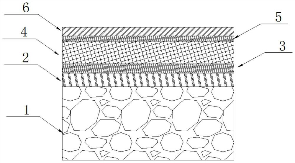
[0090] This embodiment provides a composite coating for a drill bit of a printed circuit board, and the structural schematic diagram of the composite coating is as follows figure 1 As shown, the bottom layer 2, the carbonitriding layer 3, the diamond-like coating 4 and the heat insulation layer 6 are sequentially included from the surface of the drill 1, the bottom layer 2 is a metal layer, and the heat insulation layer 6 is metal nitrogen compound ceramic layer.

[0091] The metal layer is a Ti metal layer with a thickness of 0.25 μm.

[0092] The carbonitriding layer 3 is a TiCN layer with a thickness of 0.05 μm.

[0093] The thickness of the diamond-like coating 4 is 0.5 μm.

[0094] The thermal insulation layer 6 is a TiN ceramic layer with a thickness of 0.12 μm.

[0095] The composite coating also includes a transition layer 5 located between the diamond-like coating 4 and the thermal insulation layer 6 .

[0096] The transition layer 5 is a TiCN layer with a thickne...

Embodiment 2

[0098] This embodiment provides a composite coating for a printed circuit board drill. The composite coating includes a bottom layer 2, a carbonitriding layer 3, a diamond-like coating 4 and a heat-insulating layer from the surface of the drill 1 to the outside. 6. The bottom layer 2 is a metal compound layer, and the heat insulating layer 6 is a metal nitride ceramic layer.

[0099] The bottom layer 2 is a CrN layer with a thickness of 0.5 μm.

[0100] The carbonitriding layer 3 is a CrCN layer with a thickness of 0.1 μm.

[0101] The thickness of the diamond-like coating 4 is 1.0 μm.

[0102] The heat insulating layer 6 is a CrN ceramic layer with a thickness of 0.2 μm.

[0103] The composite coating also includes a transition layer 5 located between the diamond-like coating 4 and the thermal insulation layer 6 .

[0104] The transition layer 5 is a CrCN layer with a thickness of 0.1 μm.

Embodiment 3

[0106] This embodiment provides a composite coating for a printed circuit board drill. The composite coating includes a bottom layer 2, a carbonitriding layer 3, a diamond-like coating 4 and a heat-insulating layer from the surface of the drill 1 to the outside. 6. The bottom layer 2 is a metal compound layer, and the heat insulating layer 6 is a metal nitride ceramic layer.

[0107] The bottom layer 2 is a TiN layer with a thickness of 0.05 μm.

[0108] The carbonitriding layer 3 is a TiCN layer with a thickness of 0.02 μm.

[0109] The thickness of the diamond-like coating 4 is 0.1 μm.

[0110] The thermal insulation layer 6 is a TiN ceramic layer with a thickness of 0.05 μm.


PUM

PropertyMeasurementUnit
thicknessaaaaaaaaaa
thicknessaaaaaaaaaa
thicknessaaaaaaaaaa

Abstract

The invention provides a composite coating of a printed circuit board drill point and a preparation method thereof. The composite coating sequentially comprises a bottom layer, a carbonitriding layer,a diamond-like carbon coating and a heat insulation layer from the surface of the drill point to the outside; the bottom layer comprises any one of a metal layer, an alloy layer or a metal compound layer; and the heat insulation layer is a metal nitride ceramic layer. According to the composite coating, through the design of a multi-coating structure, the hardness and abrasion resistance of the drill point can be effectively improved through the arrangement of the diamond-like carbon coating, so that the service life of the drill point is prolonged; the adhesion strength of the diamond-like carbon coating can be effectively improved through the arrangement of the carbonitriding layer, and the problem that the diamond-like carbon coating is prone to falling off is avoided; the heat insulation layer can delay graphitization of the diamond-like carbon coating, so that the service life of the drill point is further prolonged; and through deposition of a composite coating, the drill pointis particularly suitable for drilling of a high-frequency and high-speed printed circuit board, and obtained drilled holes are high in quality and precision.

Description

technical field [0001] The invention belongs to the technical field of printed circuit board processing, and relates to a composite coating for a printed circuit board drill and a preparation method thereof. Background technique [0002] With the rapid development of the electronic communication industry, especially the commercialization of 5G technology, the requirements for printed circuit board (PCB) materials are getting higher and higher. Compared with the traditional epoxy glass fiber cloth substrate, the new high-frequency high-speed board material The proportion of ceramic materials in the composition has been greatly increased. Because the ceramic material is hard and brittle and easy to break, when drilling a printed circuit board with a drill, the drill is severely worn, easy to break, and generally has a short service life, which is difficult to meet the needs of the 5G communication field. The requirements of high drilling efficiency, low wear, uniform and stabl...

Claims


Application Information

Patent Timeline
Patent Type & Authority Applications(China)
IPC IPC(8): C23C14/32C23C14/02C23C14/06C23C14/16C23C14/50C23C14/54
CPCC23C14/32C23C14/022C23C14/505C23C14/16C23C14/0664C23C14/0021C23C14/0605C23C14/0641C23C14/54
Inventor 曹时义王俊锋
Owner GUANGDONG DTECH TECH CO LTD
Why Eureka
Try Eureka