Plug-in connector

A plug connector, wire connection technology, applied in the direction of connection, conductive connection, clamping/spring connection, etc., can solve the problem of weakening elastic properties of contact rail elements, achieve good spring contact and save materials

Active Publication Date: 2011-09-21
WAGO VERW GMBH
View PDF11 Cites 6 Cited by
  • Summary
  • Abstract
  • Description
  • Claims
  • Application Information

AI Technical Summary

Problems solved by technology

However, the electrical conductivity of elastic metal alloys is not as optimal as that

Method used


Image

  • Plug-in connector
  • Plug-in connector
  • Plug-in connector

Examples


Embodiment Construction

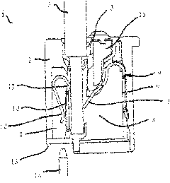
[0069] figure 1 A sectional view of a first embodiment of the plug-in connector 1 is shown in cross section. The plug-in connector 1 has a housing 2 made of insulating material, in which a wire socket 3 leading to a wire connection chamber 4 is arranged. The electrical wire 5 can be inserted into the wire connection cavity 4 through the wire insertion hole 3 .

[0070] Mounted in the conductor connection chamber 4 is a clamping spring element 6 , whose clamping leg 7 presses against the electrical conductor 5 and exerts a force in the direction of the contact pin receiving opening 8 . The clamping spring element 6 is fastened in the insulating material housing 2 via fastening legs 9 .

[0071] A busbar element 10 is mounted between the contact pin receiving opening 8 and the electrical line 5 or the line connection space 4 . The busbar element 10 has a curvature 11 protruding in the direction of the conductor connection chamber 4 in order to provide a defined, reduced conta...


PUM


Abstract

In a plug-in connector (1), at least one part of the busbar element (10) is in each case arranged in the boundary area between an associated conductor entry opening (3) and an associated contact pin receiving opening (8) in such a manner that the part of the busbar element (10) is located between a contact pin (14) and an electric conductor (5) and electrically conductively rests against the contact pin (14) and the electric conductor (5). The busbar element (10) has a resilient contact area in the contact pin receiving opening (8) for electrically contacting the busbar element (10) by a spring force with a contact pin (14) which can be inserted into an associated contact pin receiving opening (8).

Description

technical field [0001] The invention relates to a plug connector having: [0002] - a housing of insulating material, [0003] - at least one wire socket open towards the wire connection side of the plug-in connector, which respectively leads into an associated wire connection cavity in the insulating material housing for electrically conductive connection of the wires introduced into the wire socket electric wire, [0004] - each clamping spring element arranged in the conductor connection chamber has a fixing leg for fixing the clamping spring element and a clamping leg for clamping the electrical conductor, [0005] - at least one contact pin receiving opening for inserting a contact pin, each of which leads into an associated wire connection cavity and is open towards a contact pin connection side different from the wire connection side, and [0006] - a one-piece or multi-part busbar element arranged in the conductor connection chamber, which is designed in such a way ...

Claims


Application Information

Patent Timeline
IPC IPC(8): H01R13/02H01R13/24H01R4/48
CPCH01R13/15H01R4/4836H01R4/48365
Inventor 斯蒂芬·加索尔
Owner WAGO VERW GMBH
Why Eureka
Try Eureka