
Two-stage hybrid excitation brushless synchronous motor

A hybrid excitation and synchronous motor technology, which is applied to synchronous machines, controlling generators and electrical components through magnetic field changes, and can solve the problems of brushless excitation schemes that are not suitable for high-speed aviation generators, many additional air gaps for motors, and low excitation efficiency. problem, achieve the effects of simple de-excitation and fault protection methods, convenient control, and high excitation efficiency

Active Publication Date: 2013-02-06
山东智贤电器设备有限公司
View PDF3 Cites 0 Cited by
  • Summary
  • Abstract
  • Description
  • Claims
  • Application Information

AI Technical Summary

Problems solved by technology

[0003] ①The magnetic bridge of the excitation winding is installed on the stator side to provide the axial excitation magnetic field, but the motor has many additional air gaps and the excitation efficiency is low, and the material of the rotor core needs to be made of a whole piece of low-carbon steel, and the core loss is large, so it is not suitable Brushless Excitation Scheme for High-Speed ​​Aviation Generator
[0004] ②The excitation winding is directly wound on the stator to provide the excitation magnetic field, such as double salient pole hybrid excitation motor, hybrid magnetic circuit switch flux linkage motor, etc., but this type of motor is only suitable for DC generators

Method used


Image

  • Two-stage hybrid excitation brushless synchronous motor
  • Two-stage hybrid excitation brushless synchronous motor
  • Two-stage hybrid excitation brushless synchronous motor

Examples


Embodiment Construction

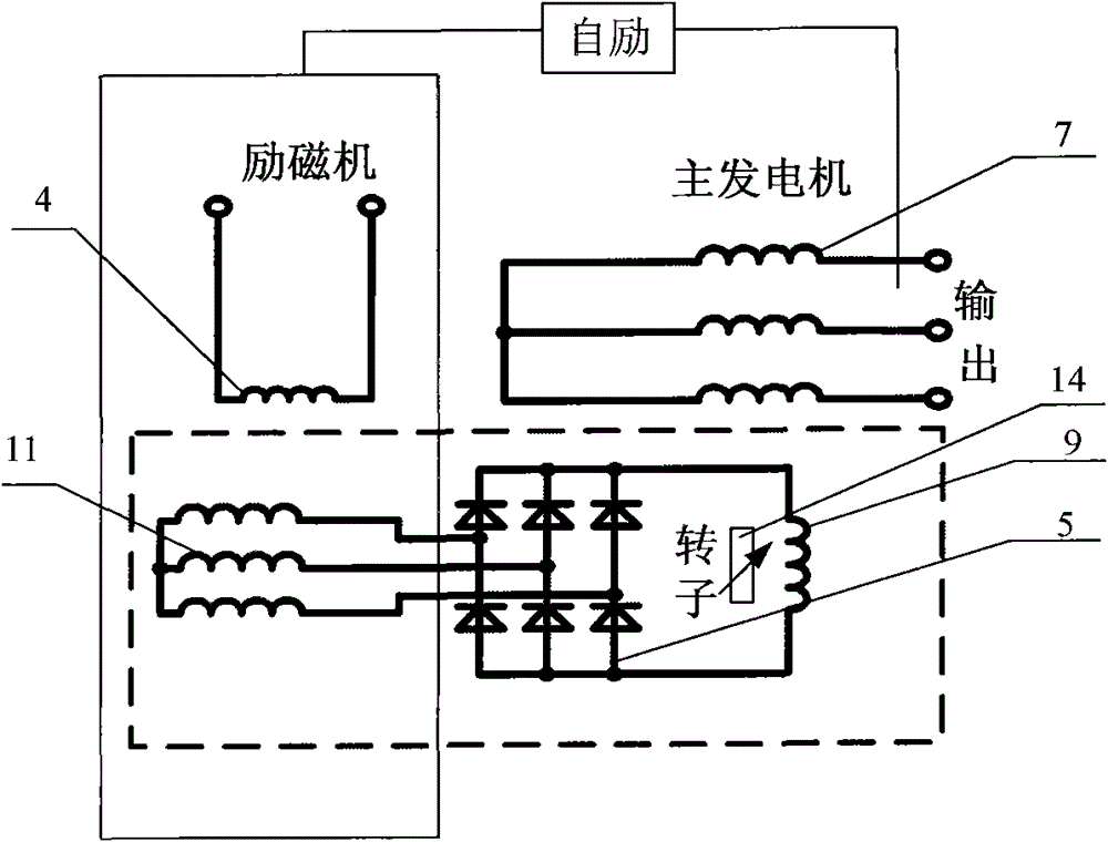
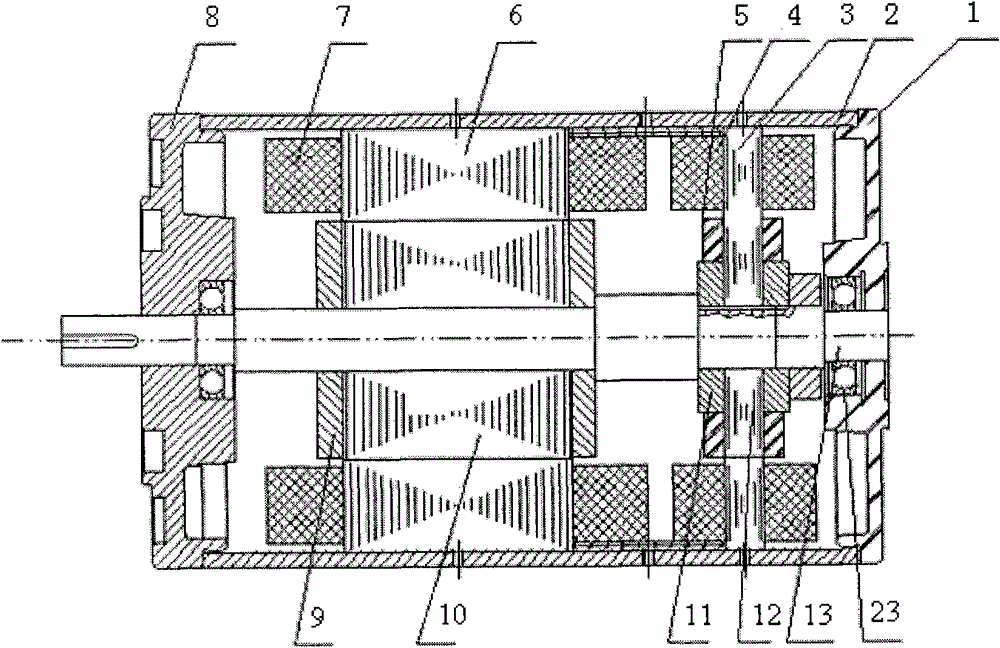
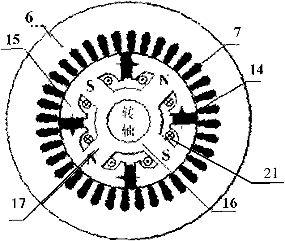
[0021] like figure 1 As shown, when the main generator is not excited, the magnetic flux generated by the permanent magnet forms a closed loop along the rotor core, thereby forming a relatively saturated magnetic field on the rotor, and a small amount of residual magnetism is closed along the stator core, resulting in residual magnetism. Voltage. This part of the electric energy is used to provide enough initial excitation energy to the exciter, so that the generator can gradually reach a stable voltage without adding additional initial excitation equipment, thus solving the problem of starting excitation of the motor. At the same time, this part of the potential can be used to power the voltage regulator and control protector, eliminating the need for a special permanent magnet auxiliary exciter. Compared with the traditional three-stage brushless structure, this scheme omits the stage of the auxiliary exciter (permanent magnet generator), and constitutes a two-stage brushle...


PUM


Abstract

The invention discloses a two-stage hybrid excitation brushless synchronous motor, which is characterized by comprising a hybrid excitation main generator, an exciter and a rotating rectifier, wherein the main generator is a rotating magnetic pole type hybrid excitation generator of which a rotor is provided with an exciting winding and a permanent magnet source; the exciter is a rotating armature type synchronous generator; an input end and an output end of the rotating rectifier are connected with an exciter armature winding and a main generator exciting winding respectively; and the rotating rectifier is arranged on the rotor. When the motor operates, alternating current generated by an exciter armature is rectified through the rotating rectifier and then is supplied to the main generator exciting winding. The invention has the advantages that: a motor exciting problem is solved without the addition of the initial excitation equipment by utilizing a permanent magnet field of the hybrid excitation main generator, so that the generator achieves stable voltage gradually and is completely self-excited. A special permanent magnet auxiliary exciter or an auxiliary exciting power supply is eliminated, and a two-stage hybrid excitation synchronous motor with a brushless structure is formed; moreover, the synchronous motor has a simple structure and high power density, and is self-excited and convenient to control.

Description

technical field [0001] The invention relates to a two-stage hybrid excitation brushless synchronous motor, which belongs to the field of the hybrid excitation brushless synchronous motor. Background technique [0002] Hybrid excitation synchronous motor is a type of motor structure first proposed by Russian scholars in the 1980s. Different from the traditional electric excitation synchronous motor and permanent magnet synchronous motor, the hybrid excitation synchronous motor has both permanent magnets and excitation windings, and two magnetic potential sources exist at the same time. It integrates the advantages of convenient magnetic field regulation and small magnetic regulation capacity of electric excitation synchronous motor and high efficiency and large torque / mass ratio of permanent magnet synchronous motor. Great promotion and application value. The rotor excitation winding of the existing hybrid excitation synchronous motor needs DC excitation, and the excitation...

Claims


Application Information

Patent Timeline
Patent Type & Authority Patents(China)
IPC IPC(8): H02P9/14H02K21/00
Inventor 朱姝姝刘力徐轶昊李兆营刘闯
Owner 山东智贤电器设备有限公司
Learn More