Accelerating pulse forming device of dielectric wall accelerator

A technology for accelerating pulses and accelerators, which is applied in the direction of linear accelerators, accelerators, electrical components, etc., can solve problems such as increased manufacturing costs of accelerators, limitations in the width of accelerated particle beams, and high technical difficulties, achieving stable and reliable operation, saving photoconductive switches, Laser saving effect

Active Publication Date: 2012-12-26
MIANYANG HONGYANG TECH
View PDF0 Cites 0 Cited by
  • Summary
  • Abstract
  • Description
  • Claims
  • Application Information

AI Technical Summary

Problems solved by technology

[0007] (1) The external DC voltage is directly applied to the outer wall of the medium beam pipe, and the capacity of the medium wall to withstand the DC voltage is much lower than the pulse voltage, resulting in a significant reduction in acceleration
If put V 0 If it is changed to a pulse voltage, its width must be hundreds of times that of the acceleration voltage pulse width, which will also greatly reduce the acceleration gradient.
[0008] (2) The pulse forming lines of multi-layer flat plates are superimposed on each other. When forming a pulse, the magnetic field formed by the pulse current will cause interference in the adjacent layer, resulting in pulse distortion
[0009] (3) A large number of photoconductive switches are used, which is not only expensive, but also makes the operation and maintenance of the accelerator difficult
[0012] (1) The withstand voltage of the drift step recovery diode is low (≤2kV). Using this device to manufacture a high-gradient accelerator will cause many structural difficulties
[0013] (2) Drift step recovery diode drive circuit is more complex and expensive
Make accelerator manufacturing cost increase substantially
[0014] (3) Similar to the first scheme, there is a problem of pulsed magnetic field crosstalk between multilayer dielectric plates
[0017] (1) A large number of lasers are used, and the output pulse width is required to be large, and the turn-on and turn-off can be accurately controlled, which is not only technically difficult, but also very expensive
[0018] (2) In this structure, the width of the accelerated particle beam is strictly limited
[0019] (3) The power supply system of the induction acceleration cavity has a complex structure, a large volume, and difficult maintenance

Method used


Image

  • Accelerating pulse forming device of dielectric wall accelerator
  • Accelerating pulse forming device of dielectric wall accelerator
  • Accelerating pulse forming device of dielectric wall accelerator

Examples


Embodiment Construction

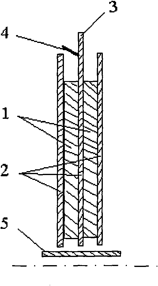
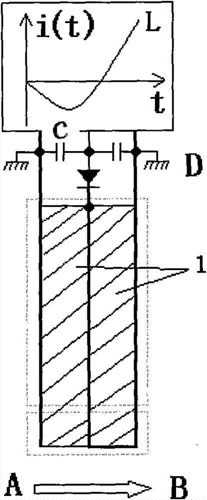
[0035] Examples of the present invention Figure 4 As shown: the accelerating pulse forming device of the dielectric wall accelerator includes three functional sections, the first functional section is the accelerating voltage pulse forming part, which consists of a dielectric plate 1, a metal electrode 2 clothed on both sides of the dielectric plate 1, and an external connection cloth in the middle of the dielectric plate 1. The power supply electrode 3 is composed of a photoconductive switch 4 between the external power supply electrode 3 and the ground electrode of the metal electrode 2; the second functional section is a matching section, and the accelerating voltage pulse forming part and the matching section use the same dielectric plate 1, and the external power supply Electrode 3 ends at the end of the accelerating voltage pulse forming part, the high-voltage electrode of the corresponding matching section is connected to the high-voltage electrode of the accelerating v...


PUM


Abstract

The invention discloses an accelerating pulse forming device of a dielectric wall accelerator. The accelerating pulse forming device comprises three functional sections, wherein the first section is an accelerating voltage pulse forming part and consists of a dielectric flat plate, metal electrodes arranged on two surfaces of the dielectric flat plate, an external power supply arranged in the middle of the dielectric flat plate, and a photoconductive switch; the second section is a matching section which is connected in parallel with the accelerating voltage pulse forming part; and the third section is a pulse voltage doubling section and is formed by overlapping at least three dielectric flat plates, wherein metal electrodes are arranged on two surfaces of each dielectric flat plate, the beginning ends of the electrodes are connected in parallel with the matching section; and the terminal ends of the transmission lines of the electrodes are connected in series with each other. The accelerating pulse forming device has the advantages that: no direct-current voltage is loaded on the wall of a dielectric pipe and the photoconductive switch is used; the obtained accelerating voltage pulse is increased by 2-4 times; the accelerating pulse forming device is simple in structure, small in volume and low in cost; the accelerating voltage pulse width can be designed arbitrarily; and the accelerating beam current is strong and the accelerating gradient is high.

Description

technical field [0001] The invention relates to a strong current particle accelerator, especially an accelerating pulse forming device of a dielectric wall accelerator with strong accelerating beam current and high accelerating gradient. Background technique [0002] After more than one hundred years of development, accelerator technology has made great progress. Accelerators of various structures play a very important role in the fields of national economic development, scientific research, medical and health care, and national defense construction. However, the current accelerators all have their shortcomings, such as low beam intensity, low acceleration gradient, or high cost, often costing billions or even tens of billions of yuan. [0003] Dielectric wall accelerator is a new type of high-gradient and strong-current accelerator concept proposed in recent years. Compared with traditional accelerators, it has many excellent characteristics. It is used for flash X-ray pho...

Claims


Application Information

Patent Timeline
Patent Type & Authority Patents(China)
IPC IPC(8): H05H7/22H05H9/00
Inventor 罗安雄
Owner MIANYANG HONGYANG TECH
Why Eureka
Try Eureka