
Stirrer of soup

A stirring device and machine body technology, which is applied in the direction of utensils with integral electric heating devices, cooking utensils, household utensils, etc., can solve the problems such as no record, and achieve the effect of convenient wiring operation

Active Publication Date: 2011-09-28
生田 一诚
View PDF11 Cites 5 Cited by
  • Summary
  • Abstract
  • Description
  • Claims
  • Application Information

AI Technical Summary

Problems solved by technology

However, in these documents, there is no description that baffles can be respectively installed on the left and right pivot parts of the drive box of the stirrer for soup (there is no motivation).

Method used


Image

  • Stirrer of soup
  • Stirrer of soup
  • Stirrer of soup

Examples


Embodiment

[0082] The baffle 24 of this embodiment uses the urging device (coil spring) 44, but the configuration of the baffle 24 may be appropriately changed in design to apply resistance of the viscous fluid to the rotating member. In addition, in this embodiment, the pump is a plunger type, but this is only an example. It is also possible for the pump to have no plunger (extrusion rod). Furthermore, it may be a pump in which the rotary inner valve having the exhaust hole is rotated 180 degrees by the driving force of the driving source, and the opening of the rotary inner valve communicates with the discharge hole (lower opening) of the outer valve. In the case of the state, the soup in the rotating inner valve flows naturally due to its own weight.


PUM


Abstract

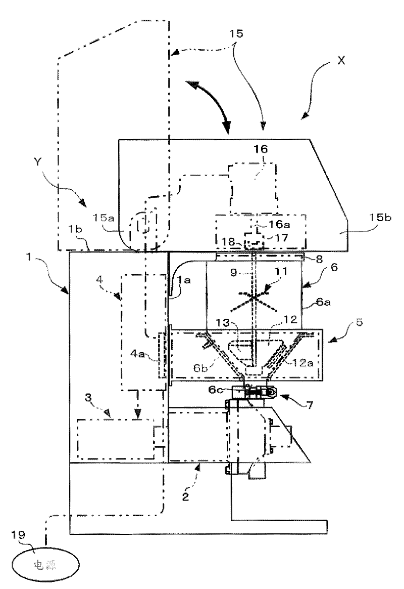
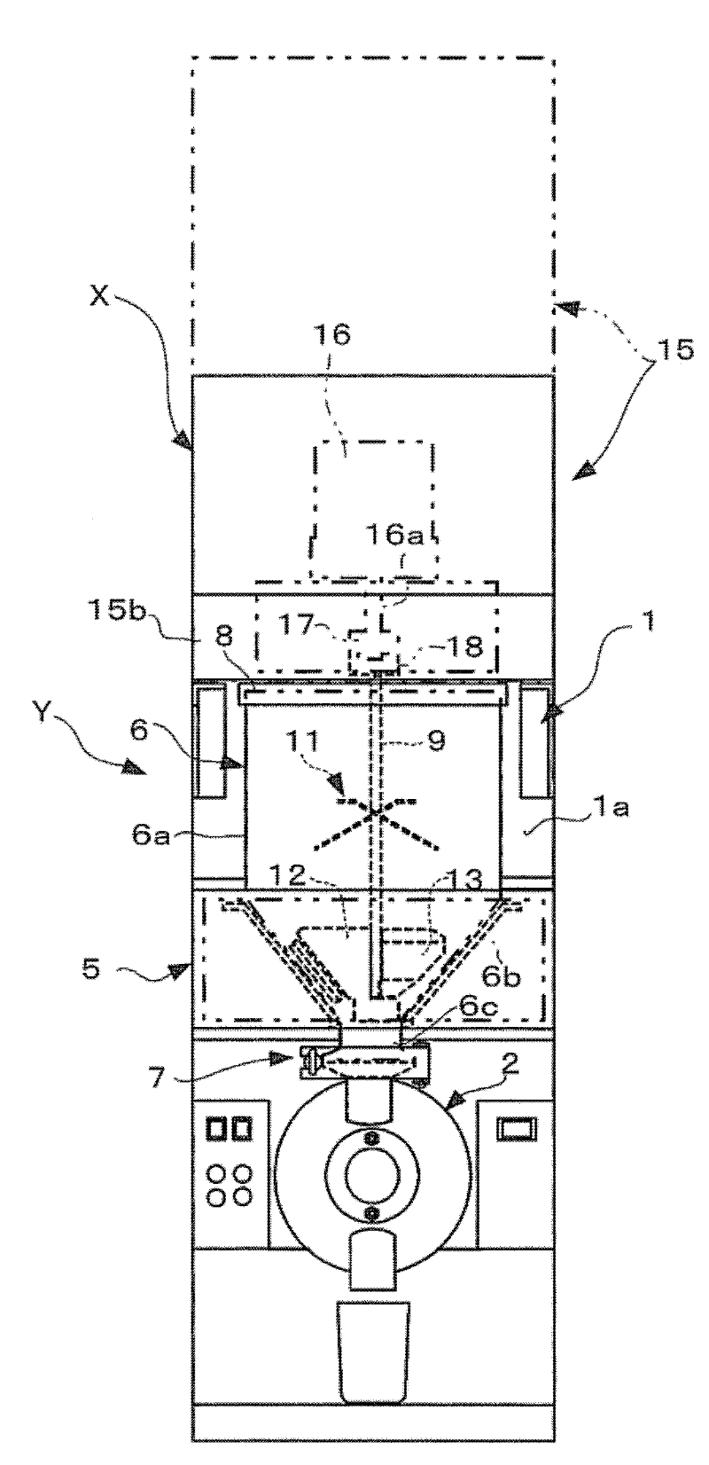
A stirrer of soup in which a pair of right and left vertical plates (22) are secured, at a predetermined interval, to the upper wall (1b) of a case-shaped body (1), and a pair of right and left supporting plates (23) are secured, at a predetermined interval, to the inner wall face at the bottom wall (31) of a drive box (15) to face these vertical plates (22). A pair of right and left dampers (24) for imparting resistance to rotation at least when the drive box (15) rotates from initial vertical state to horizontal state are attached to these supporting plates (23) and vertical plates (22). Furthermore, a pair of right and left receiving pieces (27) are secured, at a predetermined interval, to the upper end at the front wall (1a) of the case-shaped body (1) so that the bottom wall (31) of the drive box (15) can be supported when the drive box (15) becomes horizontal state.

Description

technical field [0001] The present invention relates to a stirrer for soup, and more particularly to a stirrer for soup for quantitatively supplying soup with ingredients. Background technique [0002] Patent Document 1 describes a cooling device including a stirrer for soup. In this cooling device for soup, there are: a body provided with a pump for quantitatively supplying soup and a drive source for the pump, a hopper detachably installed on the pump, and a cooling unit that is in direct surface contact with a part of the periphery of the hopper. The electronic cooling element body of the board is further composed of an annular support body integrally provided on the above-mentioned body, a control part provided on the annular support body or the above-mentioned body and supplying power to the above-mentioned cooling unit through wiring, and the above-mentioned cooling unit A plurality of them are provided at predetermined intervals along the circumferential direction in...

Claims


Application Information

Patent Timeline
Patent Type & Authority Applications(China)
IPC IPC(8): A47J27/14A23L1/39A23L23/00
CPCA47J43/044A47J43/0755A47J27/004
Inventor 生田尚之
Owner 生田 一诚
Learn More