Guidewire

A wire and single-wire technology, which is applied in the direction of guide wire, medical science, surgery, etc., can solve the problems of losing the flexibility of the front end of the wire, hindering the movement of the single wire of the coil, and perforating blood vessels, so as to ensure space, ensure flexibility, and improve flexibility. sexual effect

A wire and single-wire technology, which is applied in the direction of guide wire, medical science, surgery, etc., can solve the problems of losing the flexibility of the front end of the wire, hindering the movement of the single wire of the coil, and perforating blood vessels, so as to ensure space, ensure flexibility, and improve flexibility. sexual effect

CN102205164AInactive Publication Date: 2011-10-05ASAHI INTECC CO LTD

Image

  • Guidewire
  • Guidewire
  • Guidewire

Examples


Embodiment Construction

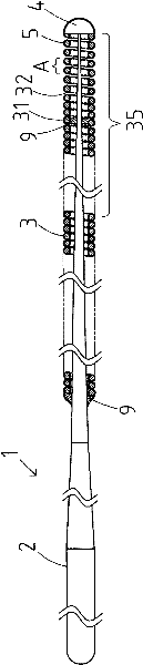
[0031] Refer below figure 1 , figure 2 The lead wire according to the first embodiment of the present invention will be described.

[0032] figure 1 It is a longitudinal sectional view showing the wire of the present invention, figure 2 is true figure 1 An enlarged partial view of part A described in .

[0033] In addition, in figure 1 In the description, for the convenience of description, the left side is referred to as a "basal end" and the right side is referred to as a "tip end".

[0034] In addition, in figure 1 In , for easy understanding, the length direction of the lead wire is shortened to schematically show the whole, so the overall size is different from the actual one.

[0035] exist figure 1 Among them, the wire 1 includes: a mandrel 2, which becomes thinner toward the front end; and a coil member 3, covering the front end of the mandrel 2, and the front end of the mandrel 2 and the front end of the coil member 3 are fixedly connected to the front end 4...


PUM


Abstract

An object of the present invention is to provide a guidewire in which the movement of coils of strand is not inhibited by a hydrophilic coating agent, and flexibility of a coiled body is secured even in a case where its coiled body is coated with the hydrophilic coating agent. The guidewire (1) includes a core shaft (2), a coiled body (3) including coils (31) of strand wound around an outer circumference of the core shaft (2), and a hydrophilic coating agent coating (5) at least a part of the coiled body. At least the part of the coiled body (3) is coated with the hydrophilic coating agent (5) so that a gap (32) may be formed between the coils (31) of strand.

Description

technical field [0001] This invention relates to wires formed with a lubricious surface. Background technique [0002] In the past, for the purpose of treatment or inspection, among guide wires used for guiding catheters inserted into tubular organs such as blood vessels, digestive tract, and urethra, or internal tissues, several types of guide wires have been proposed. The friction between the wires is provided with a hydrophilic coating on the surface of the wire. [0003] For example, Patent Document 1 (Japanese Patent Laid-Open Publication No. 2004-215710) describes a medical device comprising a metal core wire and a coil (a first coil and a second coil) provided on the end of the core wire. ) is provided with a lubricating film (hydrophilic paint) on the entire periphery of the utensil. [0004] In addition, Patent Document 2 (Japanese Patent Laid-Open Publication No. 2008-237621) describes a medical insertion instrument in which a hydrophilic polymer is provided on t...

Claims


Application Information

Patent Timeline
05 Oct 2011
Publication
CN102205164A
IPC
A61M25/09
CPC
A61L31/10; A61M25/09; A61M2025/09083; A61L31/14; A61M2025/09133; A61L2400/10
Inventors
里崎顺二