Cooling device used for vacuum forming machine

A vacuum forming machine and cooling device technology, applied in the field of home appliance equipment molds, can solve the problems of long cooling time, reduced production efficiency, insufficient cooling, etc., and achieve the effect of accelerated cooling

Inactive Publication Date: 2011-10-05
ANHUI KINGPOWER EQUIP & MOLD MFR
View PDF10 Cites 2 Cited by
  • Summary
  • Abstract
  • Description
  • Claims
  • Application Information

AI Technical Summary

Problems solved by technology

During the production of the vacuum forming machine, the plate is heated and softened and then attached to the mold to form the product. After forming, the product needs to be cooled and demolded. The existing cooling method uses a single blower to align the mold with air, and the defect is that either the cooling is not enough. Sufficient or long cooling time. When the

Method used


Image

  • Cooling device used for vacuum forming machine
  • Cooling device used for vacuum forming machine

Examples


Example Embodiment

[0013] The present invention will be further described below with reference to the accompanying drawings and embodiments.

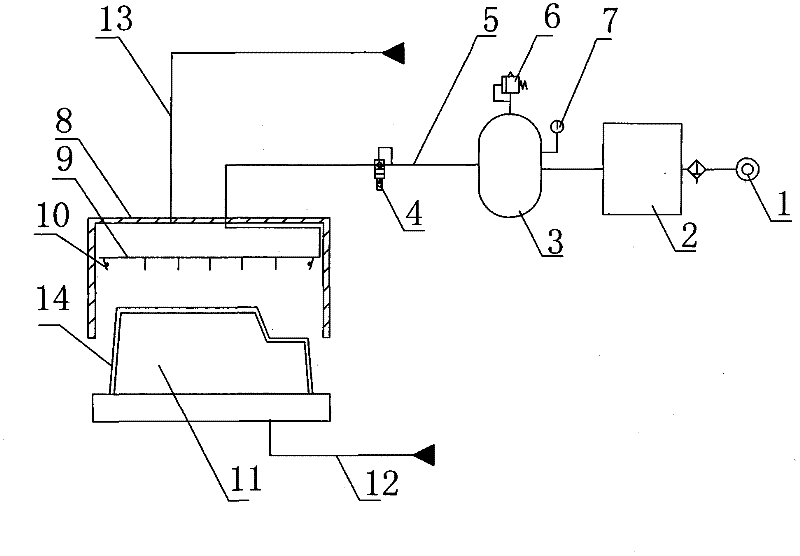
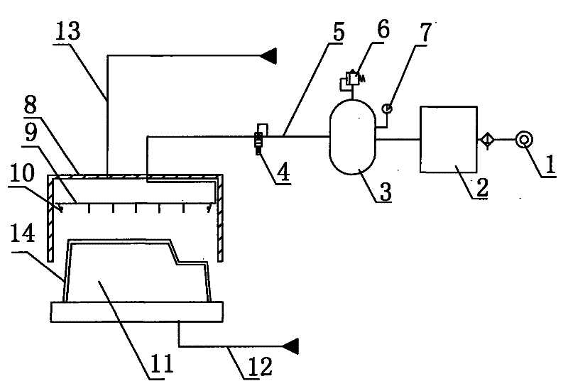
[0014] As shown in the accompanying drawings, the cooling device for the vacuum forming machine in this embodiment includes an air cooler 2, an air storage tank 3, an air supply pipe 5, an electronically controlled valve 4 arranged on the air supply pipe, and the air outlet of the air cooler 2 is connected to the The inner cavity of the air storage tank 3 is communicated, and the air storage tank 3 is communicated with the inner cavity of the sealing box 8 of the vacuum forming machine through the air supply pipeline 5 . In this embodiment, an annular pipe 9 is also arranged in the sealing box. The annular pipe 9 communicates with the air supply pipe 5. The annular pipe 9 is arranged along the inner wall of the sealing box 8 in a circle, that is, the annular pipe is rectangular and sealed The cross-sectional shape of the box 8 is the same, and a number of...


PUM


Abstract

The invention discloses a cooling device used for a vacuum forming machine. The device comprises an air cooler, a gasholder, an air supply pipeline, an electric control valve positioned on the air supply pipeline, with an air outlet of the air cooler communicated with the inner cavity of the gasholder which is communicated with the inner cavity of a seal box in the vacuum forming machine by the air supply pipeline. With the cooling device of the invention, rapid complete cooling of products can be guaranteed, and product quality and production efficiency are improved.

Description

technical field [0001] The invention relates to the technical field of household appliance equipment moulds, in particular to a cooling device for a vacuum forming machine. Background technique [0002] At present, vacuum forming machines are widely used in the electrical appliance production industry, such as the production of refrigerator (cabinet) inner liner, train interior parts, automobile interior parts and other products. When the vacuum forming machine is produced, the plate is heated and softened and then affixed to the mold to form the product. After the forming, the product needs to be cooled and demolded. The existing cooling method is to use a single blower to align the mold for air cooling. The defect is that it is not cooled or not. If the cooling time is sufficient or the cooling time is long, the formed product will continue to be cooled and deformed in the subsequent production, which will affect the quality of the product. If the cooling time is too long,...

Claims


Application Information

Patent Timeline
IPC IPC(8): B29C51/42B29C51/10
Inventor 胡德云
Owner ANHUI KINGPOWER EQUIP & MOLD MFR
Why Eureka
Try Eureka