Method and apparatus for forming amorphous coating film

Inactive Publication Date: 2009-10-01
NAKAYAMA AMORPHOUS CO LTD
View PDF19 Cites 24 Cited by
  • Summary
  • Abstract
  • Description
  • Claims
  • Application Information

AI Technical Summary

Benefits of technology

[0067]According to the method and apparatus of this invention for forming the amorphous coating film by spraying, both of the sprayed material particles and flame can be positively and sufficiently cooled, as such the material particles can be successfully changed into the amorphous coating film formed on the surface of the base material.
[0068]The cooling of the material particles and flame can be achieved by ejecting the gas, etc., toward the flame. In this case, a rate of changing the material into the amorphous state and control of occurrence of the oxides can be further improved, by properly setting or selecting the kind of each gas, manner of ejecting the gas, particle size of the

Problems solved by technology

Therefore, if not quenched at a considerably high cooling speed, such as 105K/s or so, by the so-called single roll method or the like, such amorphous alloys cannot be successfully formed.
Actually, however, it is rather difficult to cool the sprayed material so rapidly that a desired amorphous phase can be adequately created.
However, after the temperature of the material is lowered to approximately several hundred degrees, it is general

Method used


Image

  • Method and apparatus for forming amorphous coating film
  • Method and apparatus for forming amorphous coating film
  • Method and apparatus for forming amorphous coating film

Examples


Example

[0086]Hereinafter, one embodiment of the present invention will be described, with reference to FIGS. 1 to 14.

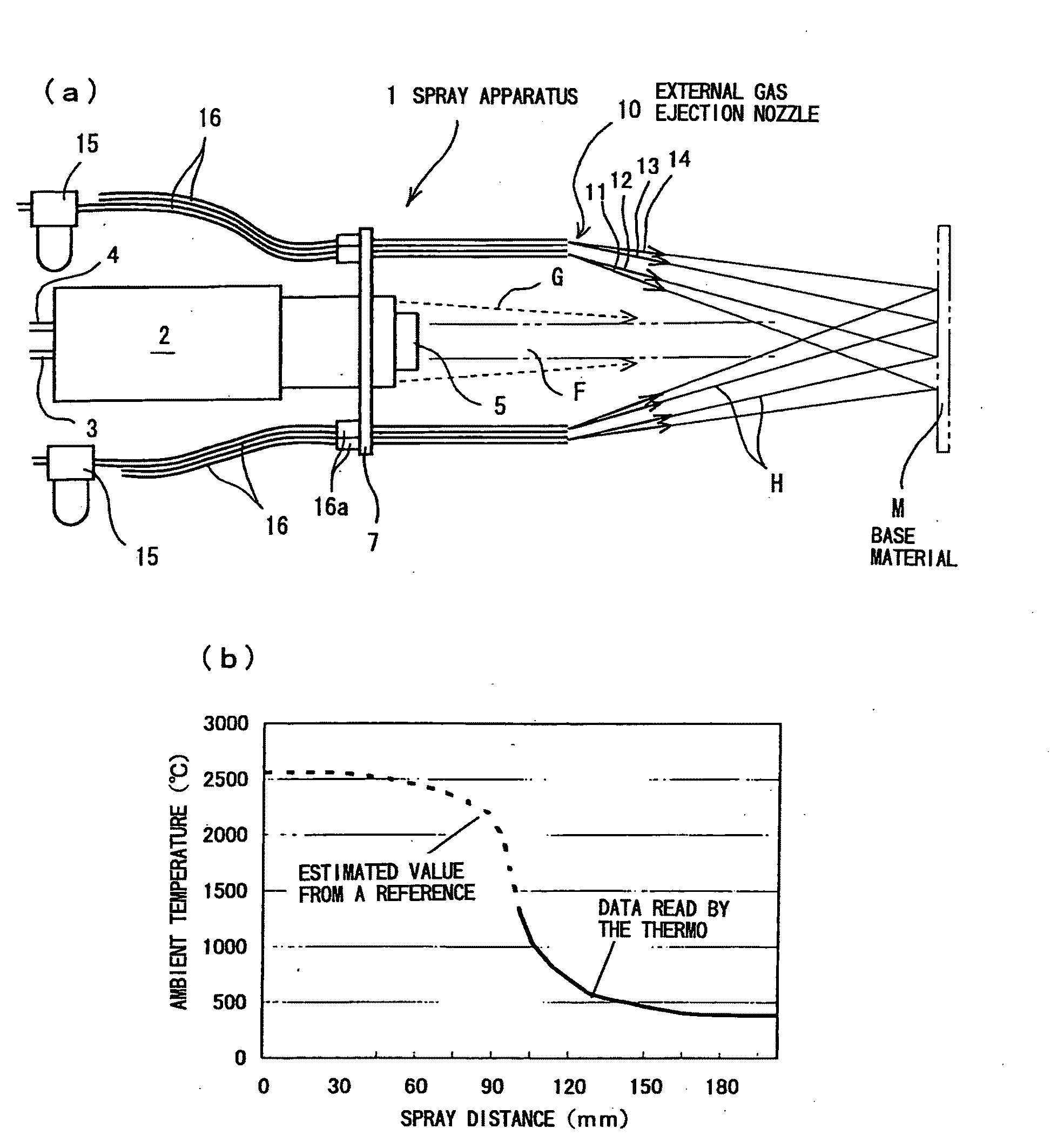
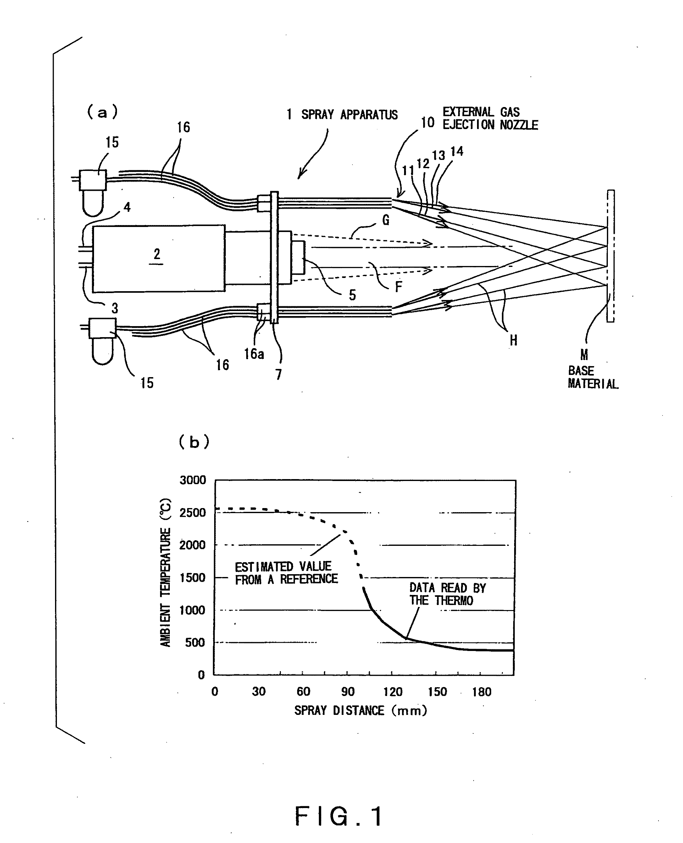
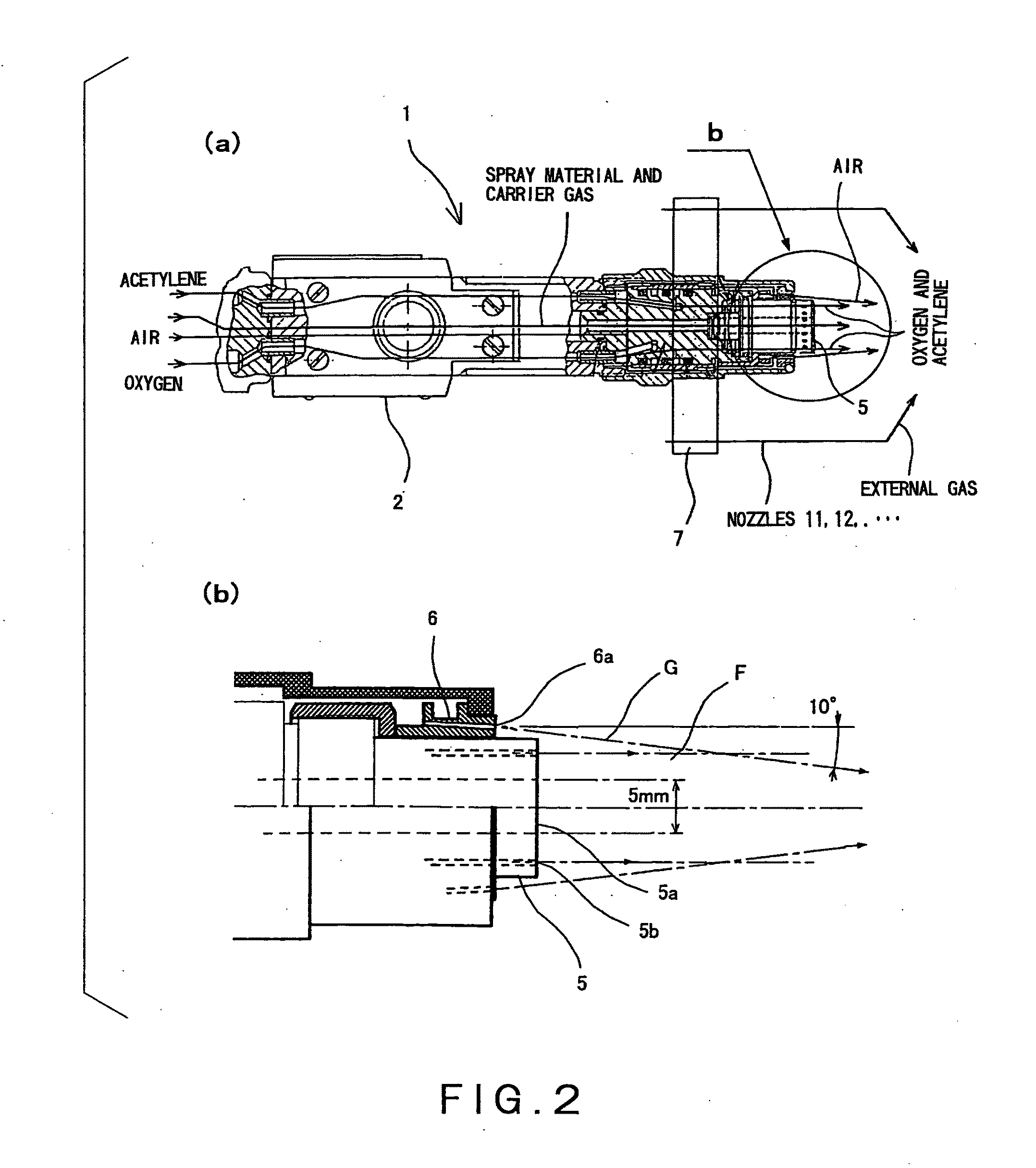
[0087]Referring first to FIGS. 1 and 2, construction of a spray apparatus 1 will be described. The spray apparatus 1 is based on a commercially available spray gun 2, and is configured for supplying fuel (acetylene and oxygen) from a gas supply pipe 3 as well as for supplying metal powder and a carrier gas from a powder supply pipe 4, to the spray gun 2. Thus, the spray apparatus 1 can eject a flame F containing a spray material (formed from the supplied and melted metal powder), in a right direction in the drawings, from a main nozzle (or burner) 5 of the spray gun 2. In the main nozzle 5, the spray material is sprayed from an ejection port 5a located at a central portion as shown in FIG. 2(b), while the flame F formed from a burned mixed gas of acetylene and oxygen (or air) is ejected from a plurality of ejection ports 5b located around the ejection port 5a.

[0088]The spra...


PUM

PropertyMeasurementUnit
Temperatureaaaaaaaaaa
Fractionaaaaaaaaaa

Abstract

The present invention provides a method and an apparatus for forming, by spraying, a commonly known amorphous coating film, which is not limited to a metallic glass or the like. According to this invention, a flame containing metal particles is ejected toward a base material from a nozzle, such that the material particles are melted with the flame. Thereafter, the melted material particles and flame are cooled before they reach the base material. For this cooling process, a gas is externally ejected toward the flame, such that the gas can gradually approach the central line of the flame. Preferably, the particle size of the material particles in the flame is within a range of 10 to 100 μm.

Description

CROSS REFERENCE TO RELATED APPLICATIONS[0001]This application is based on the prior Japanese Patent Application Nos. 2006-221112 and 2007-8477, the entire contents of which are incorporated herein by reference.TECHNICAL FIELD[0002]The present invention relates to a method and an apparatus for forming an amorphous coating film, by spraying, on a surface of a base material formed from a metal, etc.BACKGROUND ART[0003]Generally, an amorphous metal has irregular atomic arrangement different from a crystalline state, exhibits relatively high mechanical strength and corrosion resistance, and is excellent in magnetic properties. Therefore, various studies and developments have been made on a method of manufacturing such a material and use thereof. Besides, various proposals have been offered in regard to a technique for forming the amorphous coating film by spraying a material onto a surface of an object. It will be very advantageous if such an amorphous coating film can be formed by spray...

Claims


Application Information

Patent Timeline
IPC IPC(8): B05D1/10B05C11/00
CPCB05B7/205C23C4/14C23C4/124C23C4/12C23C4/129B05B7/20
Inventor KURAHASHI, RYUROUKOMAKI, MASAHIRONAGAO, NAOKO
Owner NAKAYAMA AMORPHOUS CO LTD
Why Eureka
Try Eureka