
Vibration damper with stroke-dependent damping force

A technology of shock absorbers and shock absorbers, applied in the direction of shock absorbers, springs/shock absorbers, shock absorbers, etc., can solve problems such as complete confidence in results, and achieve the effect of easy manufacturing

Inactive Publication Date: 2011-10-05
ZF FRIEDRICHSHAFEN AG
View PDF6 Cites 10 Cited by
  • Summary
  • Abstract
  • Description
  • Claims
  • Application Information

AI Technical Summary

Problems solved by technology

However, the achievable results cannot be fully assured in any case

Method used


Image

  • Vibration damper with stroke-dependent damping force
  • Vibration damper with stroke-dependent damping force
  • Vibration damper with stroke-dependent damping force

Examples


Embodiment Construction

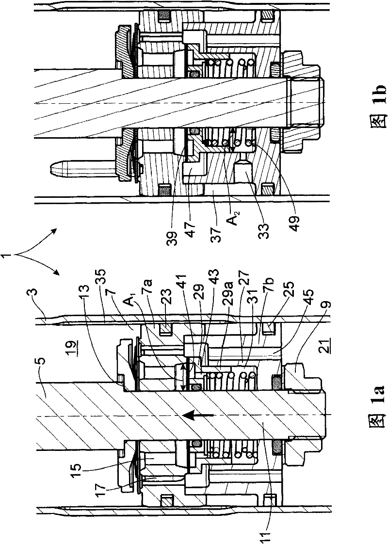
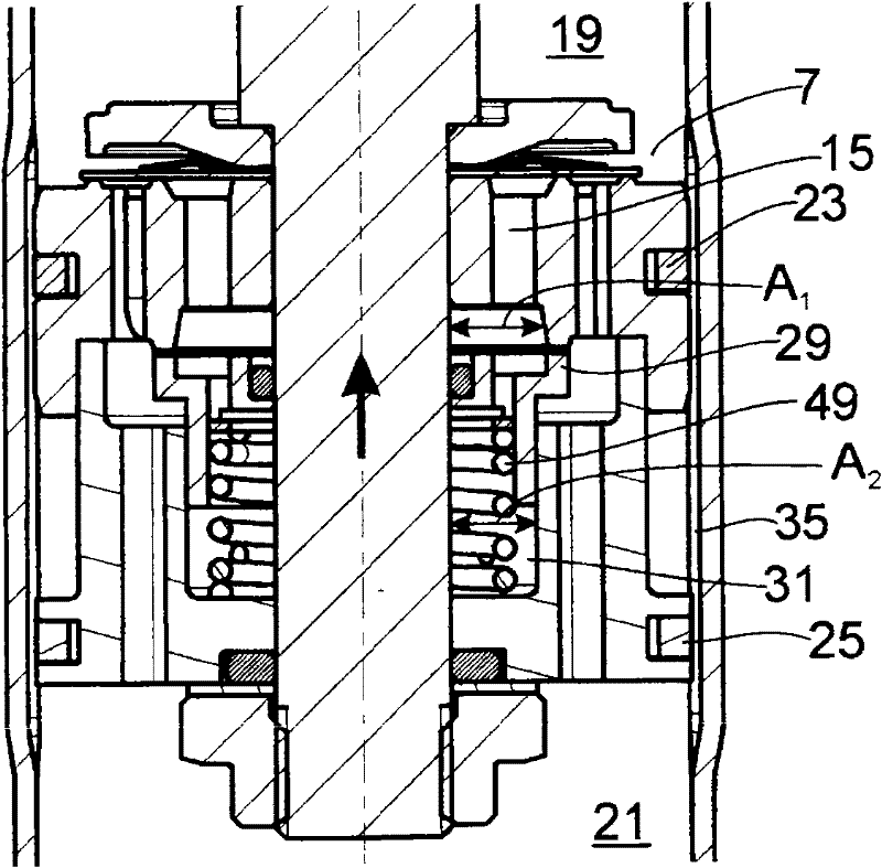
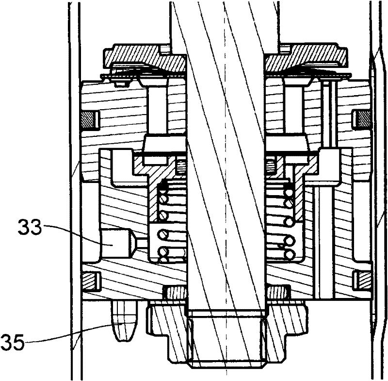
[0044] Figure 1a ; 1b shows a section of the shock absorber 1 in two different sections. A piston rod 5 with a piston 7 is guided axially movable in the cylinder 3 . In this case, it has no influence on the functionality of the invention whether this is a single-tube shock absorber or a double-tube shock absorber.

[0045] The piston 7 is designed in two parts, wherein the two piston parts 7 a , 7 b are fastened to the piston rod pin 11 at the shoulder 13 of the piston rod 5 by means of a fastening nut 9 . The first piston part 7a has separate through-flow channels 15; 17 for two opposite flow directions of the damping medium in the piston, which divides the cylinder 3 into a working space on the piston rod side and away from the piston rod. 19;21. The two working spaces 19; 21 are completely filled with damping medium and are separated by two spaced apart piston rings 23; 25 (one piston ring in each piston part).

[0046] The second piston part 7 b has a cup-shaped cross ...


PUM


Abstract

A vibration damper with stroke-dependent damping force includes a cylinder in which a piston rod with a piston is axially movable. The piston divides the cylinder into two work spaces filled with damping medium. A bypass between the work spaces is opened or closed depending on the piston position. The piston has a damping valve for at least one through-flow direction formed by a valve body that partially covers a through-flow channel in the damping valve. The valve body has first and second pressure-actuated surfaces on opposite sides of the valve body. The action of the second pressure-actuated surface depends on the position of the piston in relation to the bypass. The first pressure-actuated surface exerts a lifting force and the second pressure-actuated surface exerts a closing force on the valve disk. The second pressure-actuated surface is connected to a control space and a connection channel that overlaps with the bypass depending on the stroke position of the piston.

Description

technical field [0001] The invention relates to a shock absorber with stroke-dependent damping force according to the preamble of claim 1 shock absorber Background technique [0002] The problem of the bandwidth between the smallest and weakest damping forces and the largest and strongest damping forces prevails in conventional shock absorbers. Especially in the case of only lightly loaded vehicles, the damping force is often too high, since the likewise loaded vehicle must also be safely controlled. In order to be able to resolve this contradiction, it has long been known to use shock absorbers with slots in the working cylinder. In the event of a slight loading, the damping medium can flow by-pass around the piston on the piston rod and thus cause a drop in the damping force. However, achievable results cannot yet be fully assured in any case. [0003] It is disclosed in DE 103 43 875 A1 that a significantly greater Wide band of shock absorption. The bypass groove...

Claims


Application Information

Patent Timeline
Patent Type & Authority Applications(China)
IPC IPC(8): F16F9/48
CPCF16F9/512F16F9/483
Inventor S·海恩B·蔡斯纳
Owner ZF FRIEDRICHSHAFEN AG
Learn More