Electromagnetic mold clamping mechanism of injection molding machine

A mold clamping mechanism and injection molding machine technology, applied in the field of injection molding machine mold clamping mechanism, can solve problems such as unfavorable repetition and stability of mold clamping force, variation of mold clamping force, and influence on the final position of adsorption plate, etc., so as to eliminate potential safety hazards and ensure safety High, short power-on time effect

Active Publication Date: 2011-10-12
NINGBO HAITIAN HUAYUAN MACHINERY
View PDF5 Cites 6 Cited by
  • Summary
  • Abstract
  • Description
  • Claims
  • Application Information

AI Technical Summary

Problems solved by technology

This gap causes the screw and the nut to move slightly in the axial direction, which in turn affects the final position of the adsorption plate when the mold is closed, so that the value of the g

Method used


Image

  • Electromagnetic mold clamping mechanism of injection molding machine
  • Electromagnetic mold clamping mechanism of injection molding machine
  • Electromagnetic mold clamping mechanism of injection molding machine

Examples


Embodiment Construction

[0039] The present invention will be further described in detail below in conjunction with the accompanying drawings and embodiments.

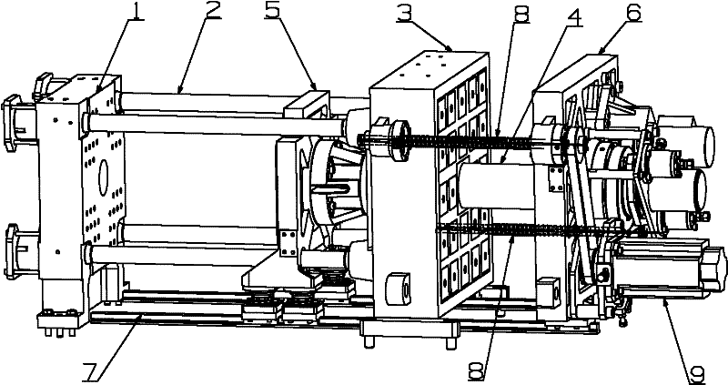
[0040] like figure 1 As shown, the electromagnetic mold clamping mechanism of the injection molding machine includes a head plate 1, a second plate 5 and a tail plate 6 arranged side by side in sequence. A magnetic plate 3 is arranged between the second plate 5 and the tail plate 6, and the magnetic plate 3 and the head plate 1 is fixedly connected via pull rod 2.

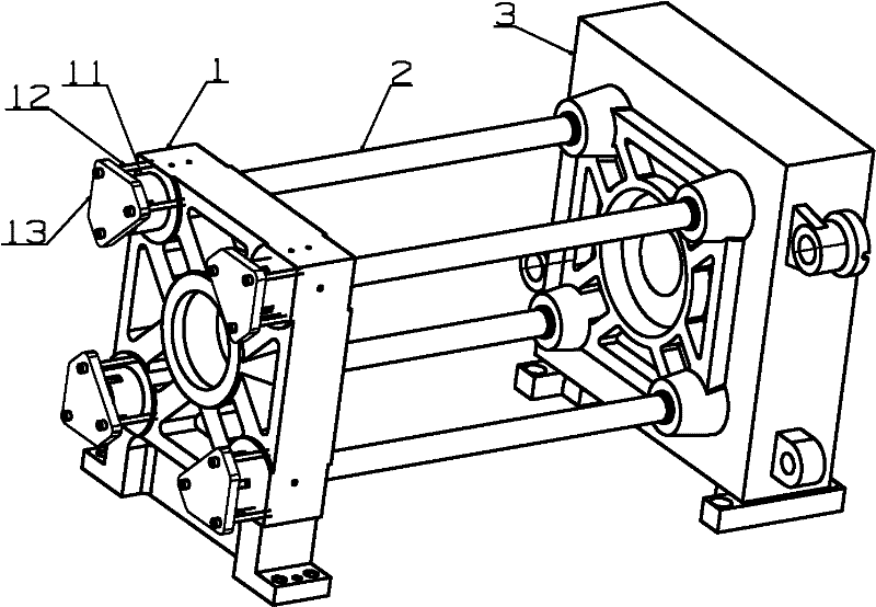
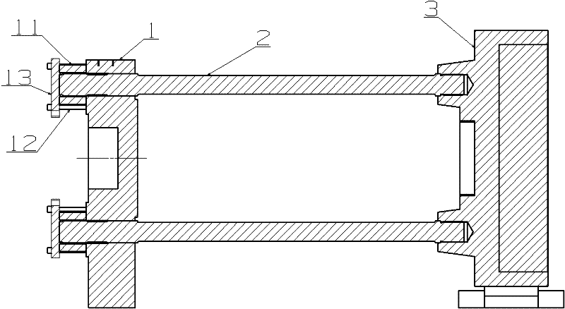
[0041] like figure 2 and image 3 As shown, the head plate 1 is fixedly installed on the fuselage, one end of four symmetrically arranged tie rods 2 is directly fixed on the magnetic plate 3, the other end passes through the head plate 1 and the head plate nut 11 is installed, and the head plate gland 13 is passed through the screw 12 Fix the head plate nut 11 on the head plate 1, so that the magnetic plate 3 is fixedly connected with the head plate 1.

[0042] like Figure 4...


PUM


Abstract

The invention provides an electromagnetic mold clamping mechanism of an injection molding machine, comprising a head plate, a secondary plate and an end plate which are sequentially arranged in parallel, wherein a magnetic plate is arranged between the secondary plate and the end plate; the magnetic plate is fixedly connected with the head plate through a pulling rod; a mold moving mechanism is arranged between the magnetic plate and the end plate; a mold adjusting column is arranged on the back of the secondary plate; the mold adjusting column is connected with a mold adjusting mechanism after penetrating through the central hole of the magnetic plate and the center of the end plate; the plane of the tail end of the magnetic plate is provided with the center hole, and is also equally provided with a plurality of magnetic poles in lines and rows; coils on the magnetic poles generate magnetic force after positively charging; the magnetic force tensions the end plate and the magnetic plate; and the coils on the magnetic poles do not generate the magnetic force to external parts after negatively charging. The mechanism has the advantages that: 1, the end plate can be equally absorbed on the magnetic plate; 2, the mechanism can strengthen the close attach between the magnetic plate and the end plate so as to ensure size and stability of mold clamping force; 3, the mechanism is energy-saving; 4, the mechanism is safe; and 5, the gap delta between the magnetic plate and the end plate is ensured.

Description

technical field [0001] The invention relates to a mold clamping mechanism of an injection molding machine, in particular to a mold clamping mechanism of an injection molding machine which adopts electromagnetic force for mold clamping. Background technique [0002] At present, there are two main mold clamping methods of the mold clamping mechanism of the injection molding machine: one is to use the pressure generated by the oil pressure to lock, and the other is to use the pressure generated by the servo motor to drive the screw to lock. [0003] There is also a mold clamping mechanism that adopts electromagnetic force to clamp molds, such as a mold clamping device disclosed in Japanese patent document CN101505941A, but it still has the following deficiencies: [0004] 1. In order to advance and retreat the movable platen, a linear motor as a first drive unit and a mold opening and closing drive unit is provided between the movable platen and the frame Fr. When a predetermi...

Claims


Application Information

Patent Timeline
IPC IPC(8): B29C45/64
Inventor 叶盛张旭民石洪曙徐碧云吴尚峰
Owner NINGBO HAITIAN HUAYUAN MACHINERY
Why Eureka
Try Eureka