
Magnetic lock

A magnetic lock and lock housing technology, applied in the field of magnetic locks, can solve the problems of poor anti-theft performance, damage resistance and environmental adaptability, which are not as good as pin locks, and inconvenient use.

Inactive Publication Date: 2011-10-12
刘新广
View PDF0 Cites 2 Cited by
  • Summary
  • Abstract
  • Description
  • Claims
  • Application Information

AI Technical Summary

Problems solved by technology

For the tumbler lock, it can be opened in a short period of time (within 50 minutes) by using some illegal master keys or opening tools without matching the key, so the technical (non-destructive) anti-theft performance is poor
Electronic locks, although technically better in anti-theft performance, have circuits and electronic devices inside, need continuous power supply, and some have to remember passwords, so it is inconvenient to use, and its anti-damage and environmental adaptability are not as good as tumbler locks.

Method used


Image

  • Magnetic lock
  • Magnetic lock
  • Magnetic lock

Examples


Embodiment 1

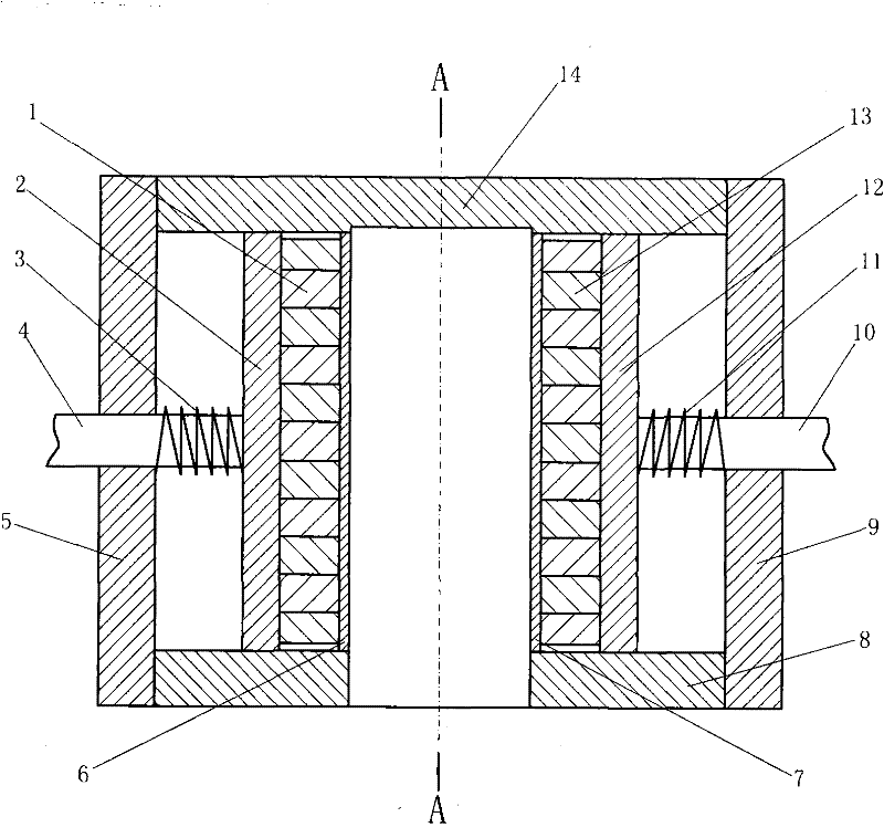
[0042] Embodiment one: the first structure of the magnetic lock, such as Figure 9 Figure 10 Show. Its magnetic lock core adopts the first kind of magnetic lock core, and its key adopts the first kind of magnetic key. Adopting described buckle mechanism is: lock hook 38 vertically passes through the center of buckle 39 and connects with it, the bottom of lock hook 38 is covered with spring 37, and buckle 39 has grab hooks drooping left and right. Insert the lower part of the lock hook 38 into the blind hole in the middle part of the non-magnetic upper plate 14 of the first type of magnetic lock core, and form a sliding fit with the blind hole, and divide the left and right drooping hooks of the buckle 39 into the first type. The left and right sides of the magnetic lock core can respectively be engaged with the clasp at the left non-magnetic bar 4 outer ends of the first kind of magnetic lock core and the clasp at the right non-magnetic bar 10 outer ends. Lock housing 36 s...

Embodiment 2

[0045] Embodiment two: the second structure of the magnetic lock, such as Figure 13 Figure 14 Show. Its magnetic lock core adopts the second magnetic lock core, and its key adopts the second magnetic key. The buckle mechanism is as follows: the lock hook 42 vertically passes through the buckle 40 and connects with it, and the spring 43 is placed on the lower part of the lock hook 42, and the buckle 40 has a left drooping hook. Insert the lower part of the lock hook 42 into the blind hole on the left side of the non-magnetic upper plate 29 of the second type of magnetic lock core, and form a sliding fit with the blind hole, and place the drooping hook on the left side of the buckle 40 in the second type. The left side of the magnetic lock core, and can engage with the clasp on the non-magnetic rod 25 outer end of the second magnetic lock core. The bottom of lock case 41 is connected with the bottom of the left side of the second magnetic lock core, and the hole on the top ...

Embodiment 3

[0048] Embodiment three: the third structure of the magnetic lock, such as Figure 17 Show. Magnetic lock core 1 uses described second kind of magnetic lock core, and the upper end of its non-magnetic bar is an inclined plane, and the non-magnetic bar here for short is dead bolt; Left support plate 48, right support plate 43 are placed in magnetic lock core 1 The left and right sides of the latch 49 respectively pass through the hole on the top of the left support plate 48, the hole on the top of the right support plate 43, and form a sliding fit with the hole, the oblique notch on the latch 49 and the dead bolt Correspondingly, the right end of the latch 49 has a slope to the left; the spring 44 is enclosed within the right portion of the latch 49 and is blocked between the right side of the right support plate 43 and the retaining ring with a retaining ring 50, and the retaining ring 50 is connected with the latch 49, But the right end slope is leaked out; the breach of the...


PUM


Abstract

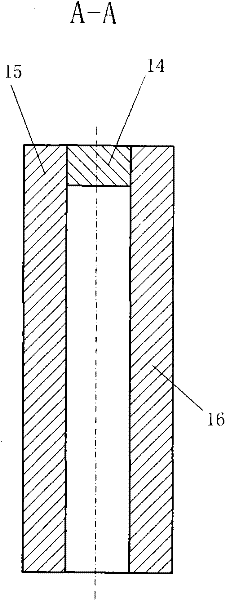
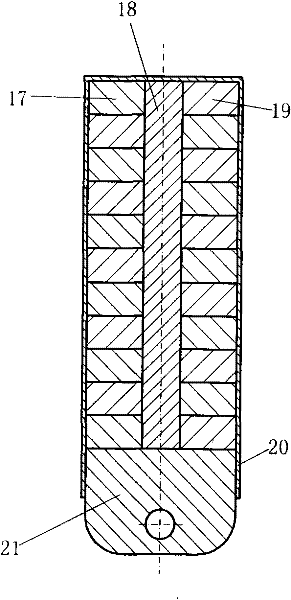
The invention discloses a magnetic lock. A lock core of the magnetic lock is characterized in that one end of a nonmagnetic rod is vertically connected with a magnetic conducting plate after sequentially penetrating through a nonmagnetic spacing plate and a pressure spring, while the other end of the nonmagnetic rod is equipped with a buckle hook; a plurality of permanent magnets are assembled on the other end surface of the magnetic conducting plate, opposite to the nonmagnetic rod; the nonmagnetic spacing plate is connected with an upper nonmagnetic plate, a lower nonmagnetic plate, a front nonmagnetic plate and a back nonmagnetic plate to form a cuboid cavity; the upper end surface, the lower end surface, the front end surface and the back end surface of the magnetic conducting plate are slidingly matched with the inner wall of the cuboid cavity; the end surfaces of the permanent magnets, in contact with the magnetic conducting plate, are one magnetic poles of the permanent magnets; and another nonmagnetic spacing plate is arranged opposite to the other magnetic poles of the permanent magnets, and is connected with each nonmagnetic plate to form key holes. A fastener mechanism with a lock hook, a clip hook and a spring is connected with the upper nonmagnetic plate; and the clip hook can be clamped and connected with the buckle hook of the nonmagnetic rod. The lock core and the fastener mechanism are both connected with a lock shell. Another magnetic conducting plate is assembled with permanent magnets as many as the permanent magnets of the lock core to form a key, wherein the same polarities of the permanent magnets on the another magnetic conducting plate and the permanent magnets of the lock core are opposite.

Description

technical field [0001] The invention relates to lock technology, in particular to a magnetic lock. Background technique [0002] Existing locksets are divided into mechanical locks and electronic locks. Most of the mechanical locks are tumbler locks, and electronic locks include face recognition or fingerprint recognition induction locks, electronic combination locks, and photoelectric electronic locks. To tumbler lock, needn't be the key that it matches, and with some illegal master key or opening tool, also can open in a short period of time (within 50 minutes), so technical (non-destructive) anti-theft performance is poor. Electronic locks, although technically better in anti-theft performance, have circuits and electronic devices inside, need continuous power supply, and some have to remember passwords, so it is inconvenient to use, and their anti-destructive and environmental adaptability are not as good as tumbler locks. Contents of the invention [0003] The prese...

Claims


Application Information

Patent Timeline
IPC IPC(8): E05B47/06E05B15/16E05B19/26E05B59/04
Inventor 刘新广
Owner 刘新广
Learn More