
Device and method for measuring electromotive force of fan motor

A fan motor, electromotive force technology, applied in the estimation/correction of motor parameters, electronic commutator, etc., can solve problems such as inability to propose solutions

Active Publication Date: 2011-10-12
IND TECH RES INST
View PDF5 Cites 4 Cited by
  • Summary
  • Abstract
  • Description
  • Claims
  • Application Information

AI Technical Summary

Problems solved by technology

Above, no effective solution can be proposed by reviewing the existing technologies

Method used


Image

  • Device and method for measuring electromotive force of fan motor
  • Device and method for measuring electromotive force of fan motor
  • Device and method for measuring electromotive force of fan motor

Examples


Embodiment Construction

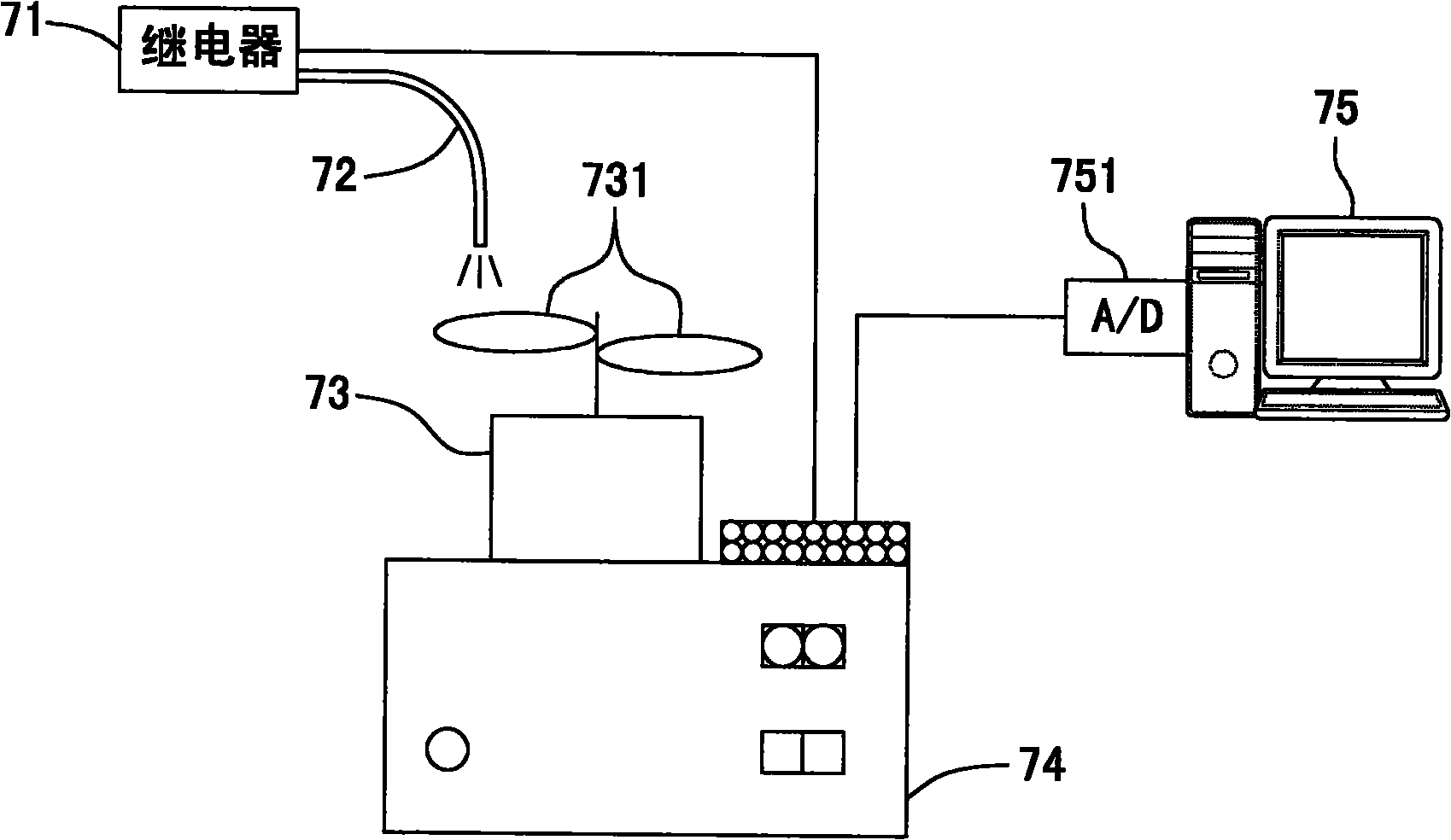
[0101] The detailed structure of the present invention and its connection relationship are described with the following drawings, so as to further describe the purpose, scheme and effect of the present invention.

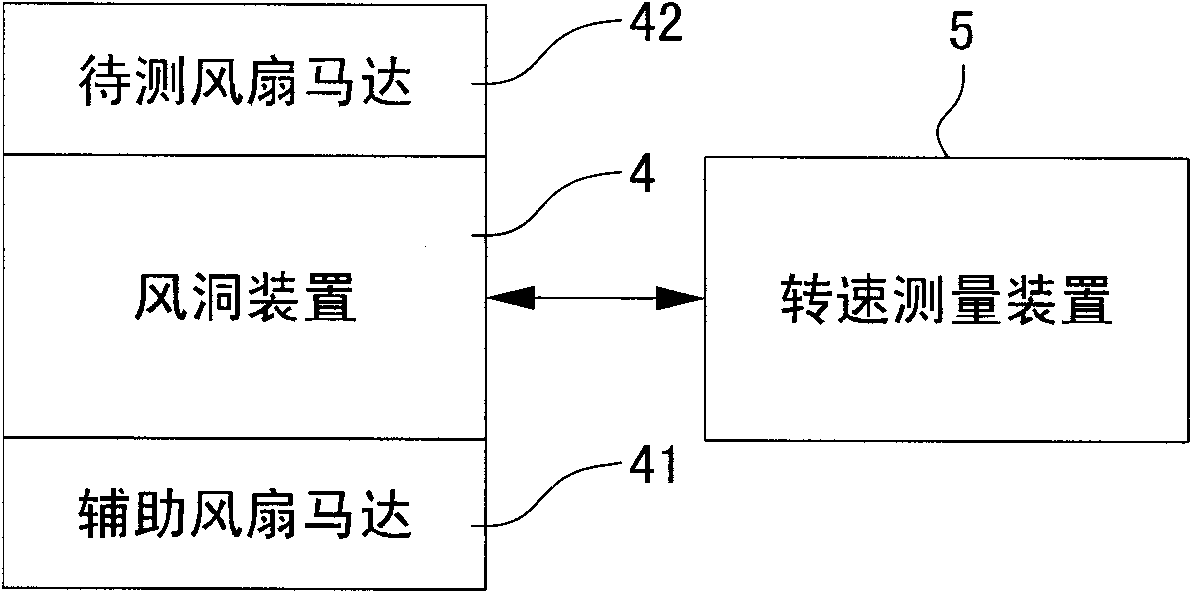
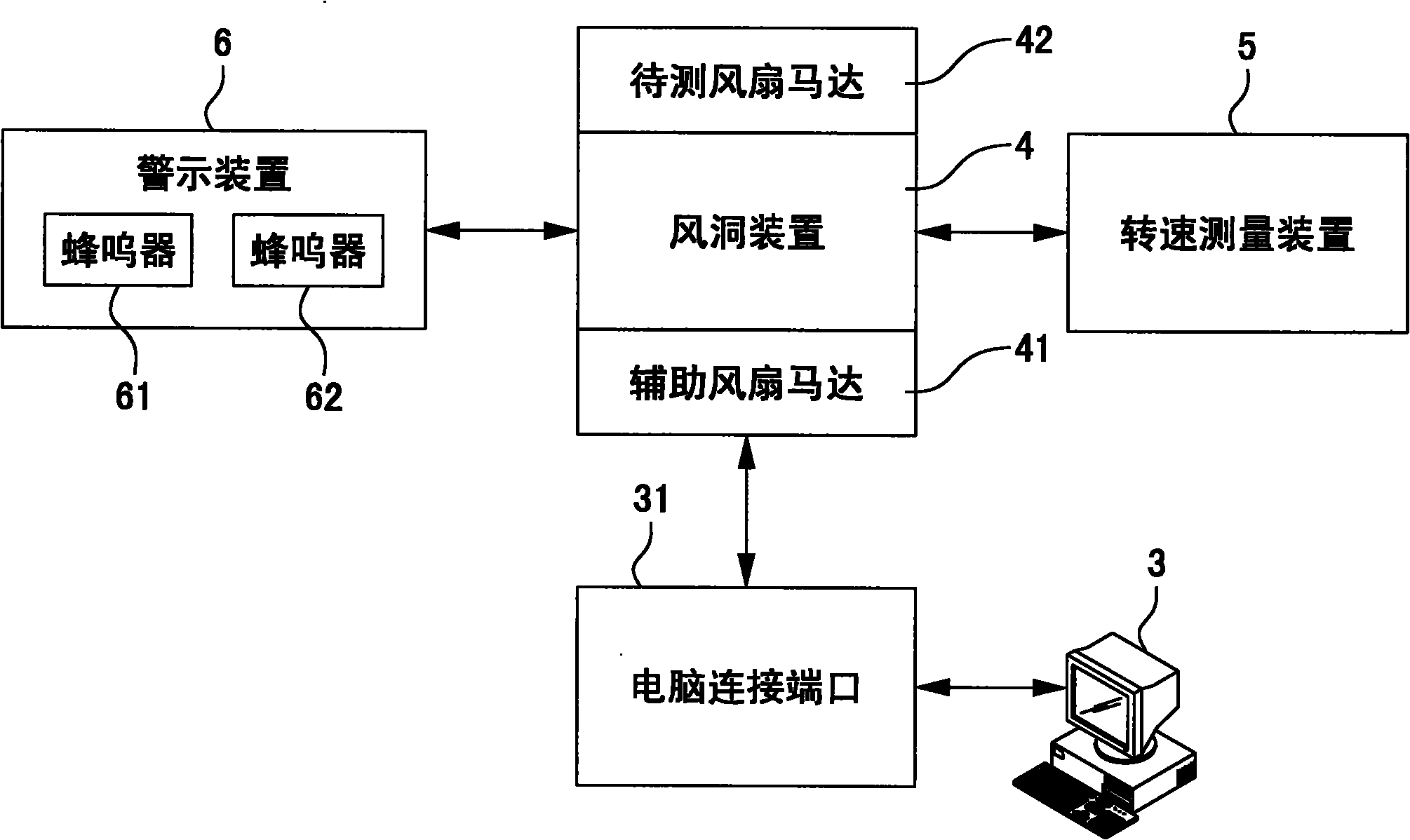
[0102] See Figure 2A Shown is a schematic diagram of the first specific implementation architecture of the fan motor electromotive force measurement device of the present invention. This embodiment does not need to be connected to a computer and is directly interpreted manually. It is suitable for a simple and low-test environment. It uses a small wind tunnel device 4 Principle: Using the auxiliary fan motor 41 to drive the flow field to drive the fan blades of the fan motor 42 to be tested in a non-contact manner, which can provide a controllable different stable fluid speed and drive the fan blades to rotate to a single or multiple different stable speeds. No additional power supply and controller are required to drive the motor to rotate, and the motor speed can be ...


PUM


Abstract

The invention discloses a device and a method for measuring an electromotive force of a fan motor. The method comprises the following steps of: generating a fluid by using a wind tunnel device capable of changing wind quantity; guiding the fan motor to be measured to rotate by the fluid; measuring a three-phase induced voltage of the motor to acquire induced electromotive force constants; and detecting whether the induced electromotive force constants meet requirements. By the method, a stable rotary speed can be obtained quickly by the fan motor to be measured; the measurement of the inducedelectromotive force constants at a rated rotary speed and at a plurality of different rotary speeds is realized without compressed air; key characteristic parameters of the fan motor to be measured are acquired; and the degree of an eddy current effect of the motor can be qualitatively observed.

Description

Technical field [0001] The invention relates to a device and method for measuring the electromotive force of a fan motor, in particular to a principle that adopts a small wind tunnel device; using a flow field to drive the fan blades in a non-contact manner, and is characterized by providing a stable fluid that can be controlled Speed, drive the fan blade to rotate to a single or multiple different stable speeds, without additional power supply and controller to drive the motor to rotate, and the motor speed can be obtained quickly and stably; when the fan motor to be tested is driven to a predetermined speed, Cooperate with an oscilloscope to measure the induced voltage and operating frequency of the motor. Background technique [0002] To test a fan motor to be tested, an auxiliary motor is usually used to drive the fan motor to be tested, and the auxiliary motor and the fan motor to be tested are pivotally connected through a coupler to make the fan motor to be tested run to t...

Claims


Application Information

Patent Timeline
IPC IPC(8): H02P6/18H02P23/14
Inventor 梁坤亿黄中隽王建昌
Owner IND TECH RES INST
Learn More