Valve and assembly method

A technology of valve sleeves and valve holes, which is applied in valve devices, transportation and packaging, valve operation/release devices, etc., can solve problems such as increasing manufacturing costs, achieve low cost, reduce logistics costs, and improve logistics quality.

Active Publication Date: 2011-10-12
ROBERT BOSCH GMBH
View PDF5 Cites 4 Cited by
  • Summary
  • Abstract
  • Description
  • Claims
  • Application Information

AI Technical Summary

Problems solved by technology

Fewer parts are required compared to single-stage logic valves, which significantly increases the manufacturing costs of the correspondingly different components (control cover, valve sle...

Method used


Image

  • Valve and assembly method
  • Valve and assembly method
  • Valve and assembly method

Examples


Embodiment Construction

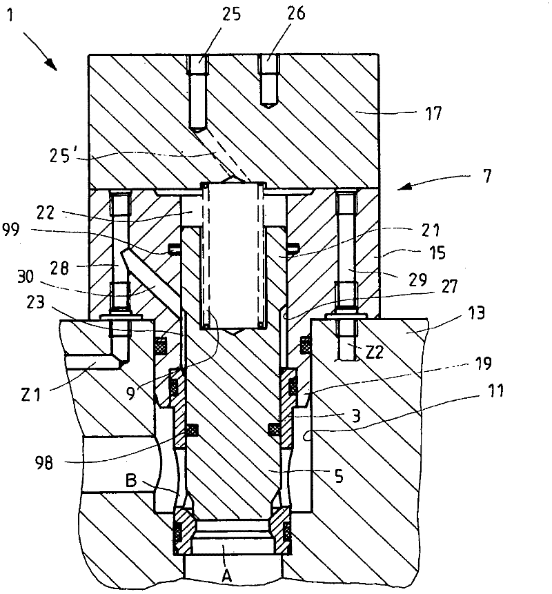
[0028] figure 1 A valve 1 applied in the hydraulic field is shown, to be precise a 2 / 2-way valve adjustable by means of an operating piston, also called an active logic valve. The valve 1 comprises a valve sleeve 3 , a valve piston 5 inserted into the valve sleeve 3 , a valve cover 7 and a spring 9 arranged between the valve piston 5 and the valve cover 7 . The valve sleeve 3 with the valve piston 5 located therein is inserted into the valve bore 11 of the control block 13 . In the control block 13 there are channels for the load connections A, B and the control connections X, Y (not shown), Z1 , Z2 of the valve 1 . The valve cover 7 is screwed onto the control block 13 above the valve hole 11 . The arrangement of the control interfaces X, Y, Z1, Z2 and the valve hole 11 complies with the German Industrial Standard DIN ISO 7368.

[0029] The valve is broadly divided into a main stage and an operating stage. The main stage is formed by a valve piston 5 inserted into the val...


PUM


Abstract

The invention relates to a valve for installation in a valve bore of a housing or valve block (13), comprising a valve bushing (3)- for insertion into the valve bore, a guided valve piston (5) that can be moved axially in the valve bushing, an activation section (21) of said piston projecting above the valve bushing axially, and a valve cover (7) that is intended to be arranged over the valve bore and that forms, together with the activation section of the valve piston, at least one activation pressure chamber (22, 23, 24). Because the valve cover is divided axially into two components - an intermediate cover (15) and a functional cover (17) with control channel - a high number of variants can be provided at little expense.

Description

technical field [0001] The invention relates to a valve for mounting in a valve bore according to the preamble of claim 1 . The invention also relates to the installation method of such a valve. Background technique [0002] Under the designation 2 / 2-way mounting valves, Bosch Rexroth AG offers seat valves or seat spool valves according to data sheets RD 21010 and RD 21050, which consist of a valve sleeve for insertion into a mounting hole according to DIN ISO 7368 and A control cover that closes the mounting hole is constructed. The spring chamber of the valve piston inserted into the valve sleeve is controlled by means of a control channel present in the control cover and possibly a pilot valve system. Valve systems, which are also described as logic valves or single-stage logic valves, have the advantage of high deformability, robust properties and low costs at high nominal volume flows. A further development of this principle leads to the construction of so-called act...

Claims


Application Information

Patent Timeline
IPC IPC(8): F16K27/02
CPCF16K27/02F16K31/1221Y10T137/5109Y10T137/5196
Inventor H·费泽
Owner ROBERT BOSCH GMBH
Why Eureka
Try Eureka