Rotary swaging forming equipment

A technology of forming equipment and forging dies, which is applied in the advanced field of material forming, can solve the problems of small impact acceleration, no diameter changing function, and large forging length of the workpiece, so as to achieve reasonable axial force and forging force, and is easy to automate Effect of controlling and mitigating impact and wear

Active Publication Date: 2011-10-19
XI AN JIAOTONG UNIV
View PDF4 Cites 24 Cited by
  • Summary
  • Abstract
  • Description
  • Claims
  • Application Information

AI Technical Summary

Benefits of technology

This patented technology describes an improved method or apparatus used for making tubular products such as pipes or bars through rotationally upsetting processes. By adding extra rolls at specific points around certain parts called inner rings, this design allows for more stable and less abrasive movements while also allowing for precise dimensions reduction without causing damage from excess pressure applied over longer periods of time. Additionally, there're no complicated structures needed inside these machines due to their simplicity and ease of use. Overall, this innovation enhances the performance and lifespan of tube manufacturing tools compared to existing methods.

Problems solved by technology

Technological Problem addressed in this patents relating to rotational forge technology includes improving the formation of thin wall tubular components such as pipes used in industrial applications like oil drilling operations due to improved fluid flow characteristics caused by reduced resistance against corrosion compared to traditional methods involving multiple steps and expensive tools. Additionally, reducing wear and tear associated with conventional techniques while maintaining desired dimensions requires more precise control over these movements.

Method used


Image

  • Rotary swaging forming equipment
  • Rotary swaging forming equipment
  • Rotary swaging forming equipment

Examples


Embodiment Construction

[0033] The present invention will be described in detail below in conjunction with the accompanying drawings.

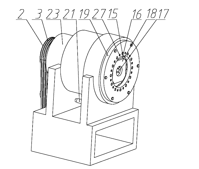
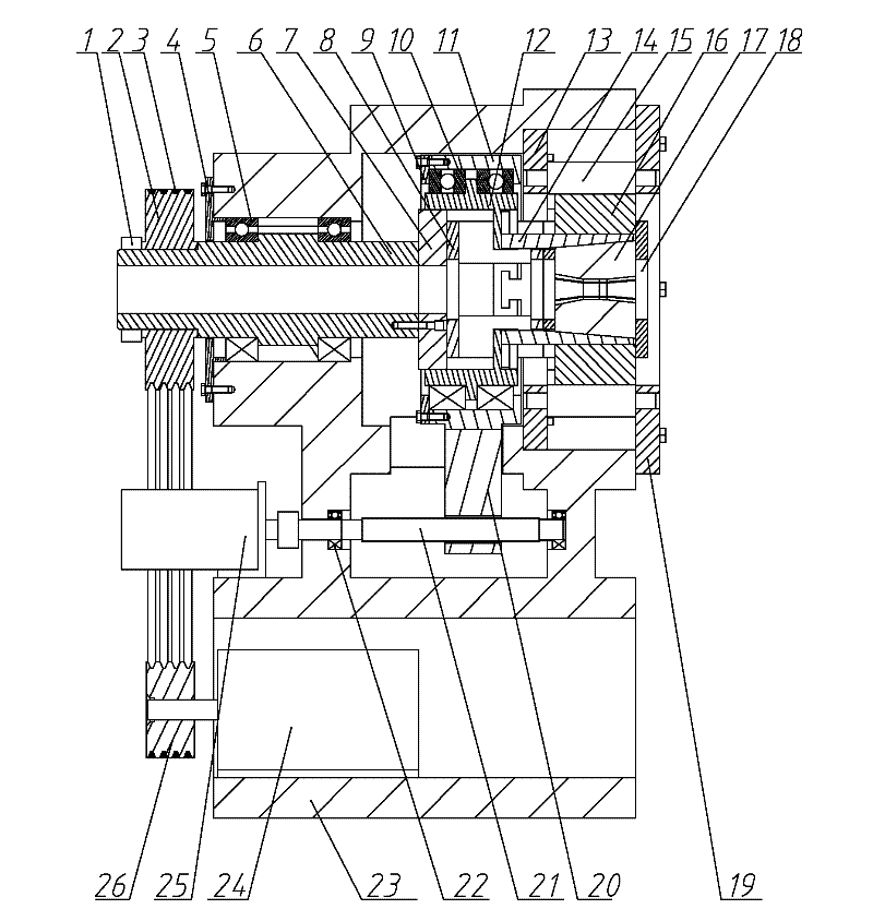
[0034] refer to figure 1 and figure 2 , a swaging forming equipment, comprising a swaging mechanism and a variable diameter mechanism, the swaging mechanism, the variable diameter mechanism, and the swaging main shaft 6 are sequentially arranged in the through hole above the main swaging main base 23, and the swaging main shaft 6 is installed in the front and rear Two deep groove ball bearings 5 ​​of the layout are driven by the swaging main motor 24 through the large pulley 2, the belt 3 and the small pulley 26, and the two deep groove ball bearings 5 ​​are installed in the swaging main frame 23 through In the hole, the swaging main motor 24 is installed on the bottom of the swaging main base 23, the swaging main shaft 6 is connected with the variable diameter mechanism connecting frame 8 in the variable diameter mechanism through the transition plate 7, and the v...


PUM


Abstract

The invention discloses a rotary swaging forming equipment, which comprises a rotary swaging mechanism and a diameter changing mechanism, wherein the rotary swaging mechanism is fixed with a rotary swaging main base through left and right pin roller mounting disks; a rotary swaging spindle is connected with a diameter changing mechanism connecting frame and a turntable respectively; forging hammers are matched with a chute in the turntable; for the curved surfaces of the forging hammers, a four symmetrical cycloid rule and a multi-point contact design are adopted; auxiliary pin rollers matched with the curved surfaces of the forging hammers are arranged between main pin rollers uniformly distributed along the circumferential direction of the rotary swaging spindle; wedge-shaped blocks in the diameter changing mechanism are matched with a chute on the end part of a wedge-shaped block slide disk; left and right lug bosses on a diameter changing mechanism pushing disk are matched with a guide rail groove on the rotary swaging main base; the diameter changing mechanism is driven by a servomotor and a ballscrew nut fitting; by designing the sizes of a neck reducing area of a forging die, a transitional fillet and a hammering work area, a workpiece is reasonably hammered. The impact of the forging hammers on the equipment during rotary swaging is reduced, the vibration and noise of the equipment are reduced, high-precision real-time diameter changing hammering can be realized, and the equipment has the advantages of high forming precision and high efficiency.

Description


Claims


Application Information

Patent Timeline
Owner XI AN JIAOTONG UNIV
Why Eureka
Try Eureka