Switching operating device and object cutting method

A technology of opening and closing action and object, which is applied in the direction of metal processing, etc., can solve the problems that the pneumatic clamp cannot directly clamp the cut part, increase the amount of discarded wires, increase the cutting process, etc., and achieve compactness of the device, easy assembly, The effect of preventing the complication of the structure

Active Publication Date: 2011-10-19
NITTOKU ENG CO LTD
View PDF5 Cites 1 Cited by
  • Summary
  • Abstract
  • Description
  • Claims
  • Application Information

AI Technical Summary

Problems solved by technology

Therefore, even if the pneumatic clamp clamps the vicinity of the cut portion of the electric wire cut by the pneumatic cutter, the pneumatic clamp cannot directly clamp the cut portion.
In addition, there is a problem that the cut end of the electric wire located in front of the part clamped by the pneumatic clamp becomes a free end, which makes the operation difficult.
In order to eliminate this problem, for the purpose of making the air clamp clamp the end of the electric wire, although it can be considered to cut off the free end of the electric wire in front of the clamping part of the air clamp again, if the free end is cut again It will increase the cutting process, resulting in the problem of increasing the amount of discarded wires

Method used


Image

  • Switching operating device and object cutting method
  • Switching operating device and object cutting method
  • Switching operating device and object cutting method

Examples


Embodiment Construction

[0020] Hereinafter, the best mode for carrying out the present invention will be described based on the drawings.

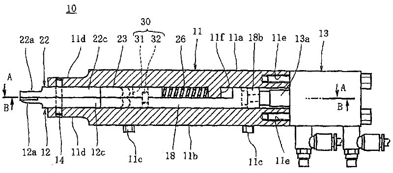
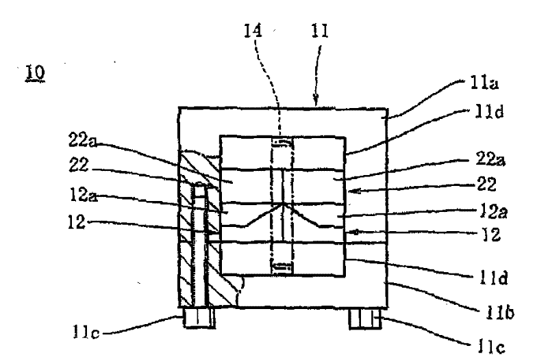
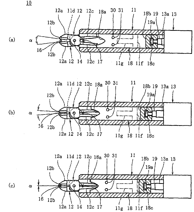
[0021] figure 1 The opening and closing operation device 10 of the present invention is shown in . The opening and closing operation device 10 includes a cylindrical body 11 and a pair of cutting rods 12 pivotally supported on the front end of the body 11 . Such as figure 2 As shown, the body 11 is formed into a square tube shape by attaching the second body part 11b to the U-shaped opening of the first body part 11a having a U-shaped cross section with small screws 11c. The second body part 11b blocks the opening of the first body part 11a.

[0022] Such as figure 1 and figure 2 As shown, at the front end of the fuselage 11, a pair of shaft support portions 11d, 11d, which are parallel to each other at a predetermined interval, protrude forward in order to sandwich a pair of cutting rods 12, 12 from both sides and perform shaft support. formed. In addit...


PUM


Abstract

The invention provides a switch operating device. The switch operating device comprises a frame (11); a pair of cutting rod bodies (12) axially supported on the front of the frame (11) and forming a cutting part (12a) on the top side; and a cutting slide block (18) driven by a driving mechanism (13) to move and making the cutting part perform switch operations. The device further comprises a pair of clamping rod body (22) located adjacent to the pair of cutting rod bodies, axially supported on the front of the frame (11) and forming a clamping part (22a) located on the top side and side by side with the cutting part; a clamping slide block (23) located adjacent to the cutting slide block (18), slidingly accommodated in the frame (11) and making the clamping part to perform switch operations by moving in the same direction as the cutting slide block (18) does; a force application unit (26) for exerting force on the clamping slide block (23) towards a direction where the clamping slide block performs closing operations to the clamping part; a relative movement limiting unit (30) limiting the relative movement of the cutting slide block (18) and the clamping slide block (23) and banning that the stretching angle of the clamping part is smaller than that of the cutting part.

Description

technical field [0001] The present invention relates to an opening and closing device used as pneumatic cutters, pneumatic clamps, etc., and a method for cutting an object using the opening and closing device. Background technique [0002] Conventionally, the following device is known (for example, refer to Patent Document 1) as a pneumatic nipper used in an assembly line of electrical components or in a field where the edge of a cloth material is cut, and includes: a tubular machine body; a pair of cutting rods, which are pivotally supported on the front end of the fuselage, and a cutting part is formed on the top side protruding forward from the front end of the fuselage; a slider for cutting, which is slidably accommodated in the fuselage, passes Air pressure moves the cutting part to open and close. The slider for cutting is configured to move inside the machine body by air pressure, and the opening angle of the cutting part is reduced by the movement of the slider so t...

Claims


Application Information

Patent Timeline
Patent Type & Authority Applications(China)
IPC IPC(8): B26D7/26B26D5/12
Inventor 押野忠良
Owner NITTOKU ENG CO LTD
Why Eureka
Try Eureka