Hydraulic ice raker

An ice raking and hydraulic technology, used in water conservancy projects, open water surface cleaning, construction, etc., can solve problems such as poor work safety, low labor efficiency, and poor flow of water, and achieve good ice removal effect, reliable performance, well-structured effect

Active Publication Date: 2011-10-19
安徽水利开发有限公司 +1
View PDF4 Cites 6 Cited by
  • Summary
  • Abstract
  • Description
  • Claims
  • Application Information

AI Technical Summary

Problems solved by technology

[0002] In cold weather, there will be ice floes in the lock chambers of water conservancy projects or channel projects. When the above projects discharge or transport water, a large number of floating ice will cause blockage of the lock chambers and poor flow of water.
At present, manual cleaning has been used to deal with the floating ice in the lock chamber, which has the problems of low labor efficiency, high labor intensity, and poor work safety.

Method used


Image

  • Hydraulic ice raker
  • Hydraulic ice raker
  • Hydraulic ice raker

Examples


Embodiment Construction

[0014] The present invention is further described below in conjunction with embodiment and accompanying drawing.
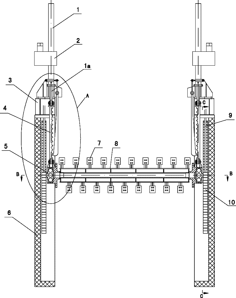
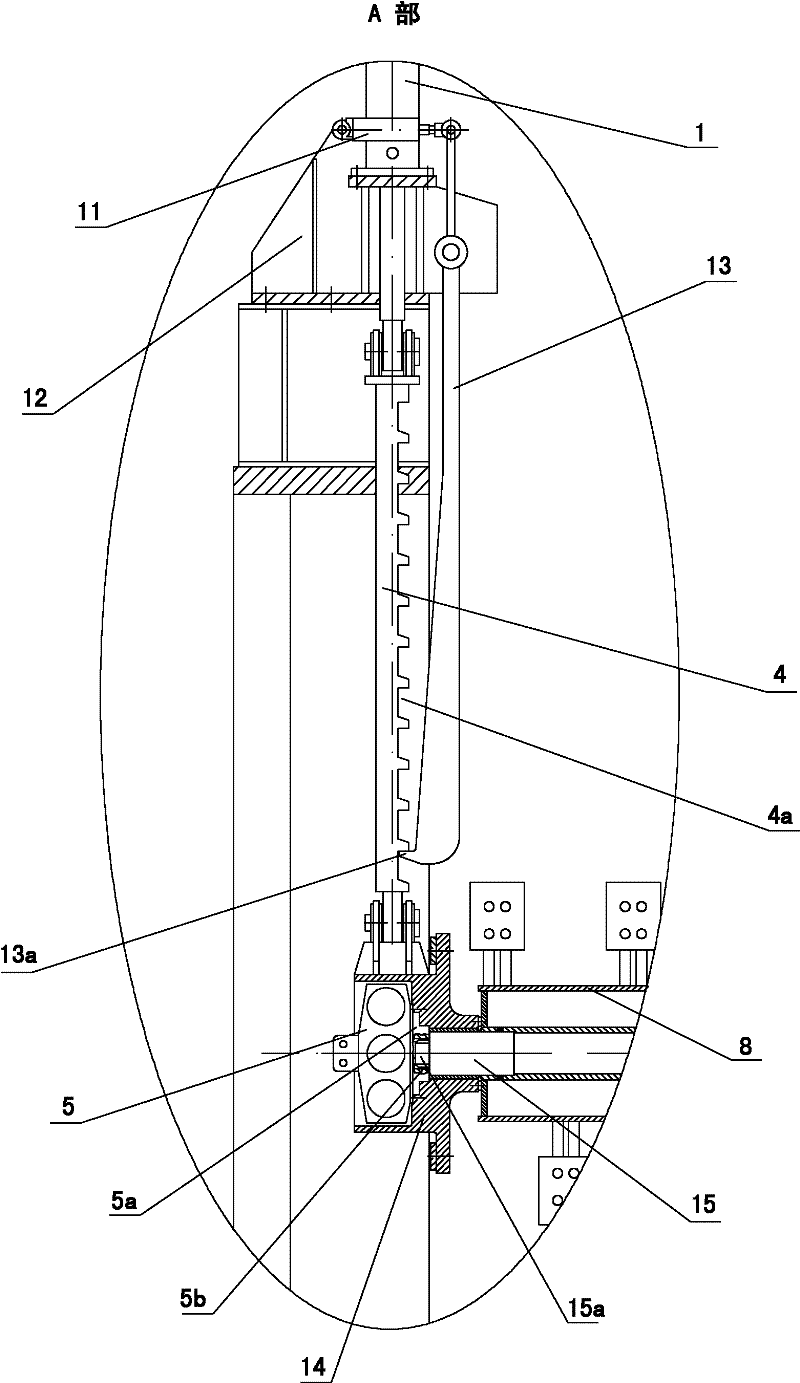
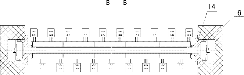
[0015] see figure 1

[0016] The electric ice raking machine provided by the present invention has a pair of vertical rails 6 arranged oppositely. A hydraulic cylinder 1 is respectively arranged on the upper end of each rail 6. The front end of the piston rod 1a of the hydraulic cylinder 1 is downward, and the piston of each hydraulic cylinder The front end of the rod 1a is hingedly connected to the upper end of the pull rod 4 in the corresponding track 6 , and a hydraulic motor 5 is connected to the lower end of each pull rod 4 . The two ends of a drum 8 arranged between a pair of rails 6 are respectively connected with the rotating shaft of a hydraulic motor 5 , and more than two groups of rake teeth 7 are arranged on the outer side of the drum 8 . In addition, the integrated hydraulic drive device 2 matched with the hydraulic cylinder 1 is fixed outside the c...


PUM


Abstract

The invention discloses a hydraulic ice raker; a pair of vertical tracks are oppositely arranged; the upper end of each track is provided with a hydraulic cylinder; the front end of a piston rod of the hydraulic cylinder faces downwards; the front end of the piston rod of each hydraulic cylinder is connected with the upper end of a pull rod in the corresponding track; the lower end of each pull rod is connected with a hydraulic motor; two ends of a rotary drum arranged between one pair of tracks are connected with a rotation shaft of the hydraulic motor; and more than two groups of rake pawls are arranged at the outer side of the rotary drum. The hydraulic ice raker is arranged at lock chambers at two sides of a gate in riverway fork; when an ice discharging brake at the rear side of the gate is closed and more floating ice accumulates on the water surface, the hydraulic cylinder drives the rotary drum to move to the water surface, the motor is started, the rake pawls on the rotating rotary drum can crush the floating ice in the lock chamber and push the floating ice to the ice discharging brake, and the accumulated floating ice can cross the ice discharging brake under the pushing of the rake pawls along with the continuous rotation of the rotary drum so as to fall to the downstream.

Description

technical field [0001] The invention relates to equipment for clearing lock chambers on both sides of gates in water conservancy projects and canal projects, in particular to a hydraulic ice rake machine for clearing floating ice in lock chambers in cold weather. Background technique [0002] In cold weather conditions, there will be ice floes in the lock chambers of water conservancy projects or canal projects. When the above-mentioned projects discharge or transport water, a large number of floating ice will cause the lock chambers to be blocked and the flow of water will not be smooth. At present, manual cleaning has been used to deal with the ice floes in the lock chamber, which has the problems of low labor efficiency, high labor intensity and poor work safety. Contents of the invention [0003] The object of the present invention is to provide a hydraulic ice raking machine, which can efficiently clean the floating ice in the lock chamber. [0004] In order to achie...

Claims


Application Information

Patent Timeline
Patent Type & Authority Applications(China)
IPC IPC(8): E02B15/02
Inventor 王孝虎江国祥路跃张小龙赵勇平
Owner 安徽水利开发有限公司
Why Eureka
Try Eureka