Vortex cleaning drill pipe

A drill pipe and vortex technology, applied in the direction of drill pipe, drill pipe, drilling equipment, etc., to achieve the effect of improving rock-carrying efficiency, enhancing rock-carrying ability, and improving flow characteristics

Inactive Publication Date: 2011-10-19
SHANGHAI UNIV
View PDF7 Cites 2 Cited by
  • Summary
  • Abstract
  • Description
  • Claims
  • Application Information

AI Technical Summary

Problems solved by technology

[0004] At present, the drilling tools for cleaning the cuttings bed are basically based on the structure of ordinary drill pipes, and then improve its structural

Method used


Image

  • Vortex cleaning drill pipe
  • Vortex cleaning drill pipe
  • Vortex cleaning drill pipe

Examples


Embodiment 1

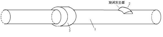
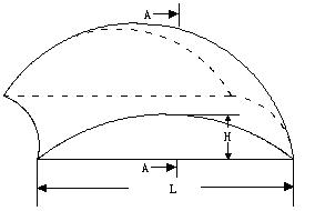
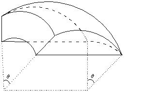
[0024] Example 1: see Image 6 , This vortex cleaning drill pipe is a drill pipe body (1) with a set of symmetrical vortex generators 2, see figure 2 with image 3 , The vortex generator 2 is a bar raised on the surface of the drill pipe body (1), the height of the bar Range is 1~19mm, length The range is 20cm~50cm, the central angle corresponding to the width of the contact with the drill pipe surface At 10~60°, the center angle corresponding to the end face width is 10~82°, and there is a smooth transition between the length direction and the drill pipe surface. See the corresponding annular space annulus structure Figure 7 , See the corresponding flow field vortex diagram Figure 8 .

Embodiment 2

[0025] Example 2: see Picture 9 , This vortex cleaning drill pipe is a drill pipe body (1) with two sets of symmetrical vortex generators (2), the vortex generators (2) are blade-shaped, and the upper and lower drill pipes are connected by a drill pipe joint (3). The corresponding annular space gas streamline diagram is shown in Picture 10 .

[0026] The principle is as follows:

[0027] The invention uses the vortex generator to not only generate vortices, but also effectively increase the tangential velocity of the gas in the annular space. Therefore, the vortex cleaning drill pipe can effectively improve the rock-carrying effect of the annular space in the horizontal well section and reduce the possibility of formation of cuttings beds. . figure 2 The specific structure of the vortex generator is given. figure 1 It is a structure diagram of a vortex cleaning drill pipe with a single vortex generator. Figure 5 It is a vortex diagram in a section near a single vortex generato...


PUM

PropertyMeasurementUnit
Heightaaaaaaaaaa
Lengthaaaaaaaaaa

Abstract

The invention relates to a vortex cleaning drill pipe. The drill pipe comprises a drill pipe body (1), wherein a vortex generator (2) is arranged on the surface of the drill pipe body and can generate lots of vortexes with different sizes, quantities and ranges in an annular space around the drill pipe, so that the cuttings in annular space, which are deposited at the low side of a borehole, are taken to the center of the annular space and finally taken away by gas in the annular space. Therefore, the possibility of formation of a cuttings bed on the horizontal segment of a horizontal well is effectively reduced.

Description

Technical field [0001] The invention relates to a vortex cleaning drill pipe, particularly a vortex generated by a vortex generator to improve the efficiency of gas carrying in the annular space of a horizontal well, which is useful for solving the problem of cuttings bed that may occur in the annular space of the horizontal section of the horizontal well. It has very important on-site guidance significance. Background technique [0002] The cuttings bed is a unique phenomenon of horizontal wells, that is, in the eccentric annular space, due to the small air velocity in the small annular space and the cuttings particle size is large enough, the cuttings bed is formed in the direction of the borehole wall in the horizontal section. However, the presence of the cuttings bed can easily cause downhole accidents, which will seriously affect the normal operation of drilling. The vortex cleaning drill pipe mainly relies on its special geometric structure to control the change of the an...

Claims


Application Information

Patent Timeline
IPC IPC(8): E21B17/00
Inventor 狄勤丰姚建林王文昌
Owner SHANGHAI UNIV
Why Eureka
Try Eureka