Electrical machine and permanent-magnet

A permanent magnet, magnet technology, applied in the field of synchronous machines, can solve difficult and expensive problems

Active Publication Date: 2011-10-19
SIEMENS GAMESA RENEWABLE ENERGY AS
View PDF5 Cites 7 Cited by
  • Summary
  • Abstract
  • Description
  • Claims
  • Application Information

AI Technical Summary

Problems solved by technology

It is very difficult and expensive to manufacture this geometry

Method used


Image

  • Electrical machine and permanent-magnet
  • Electrical machine and permanent-magnet
  • Electrical machine and permanent-magnet

Examples


Embodiment Construction

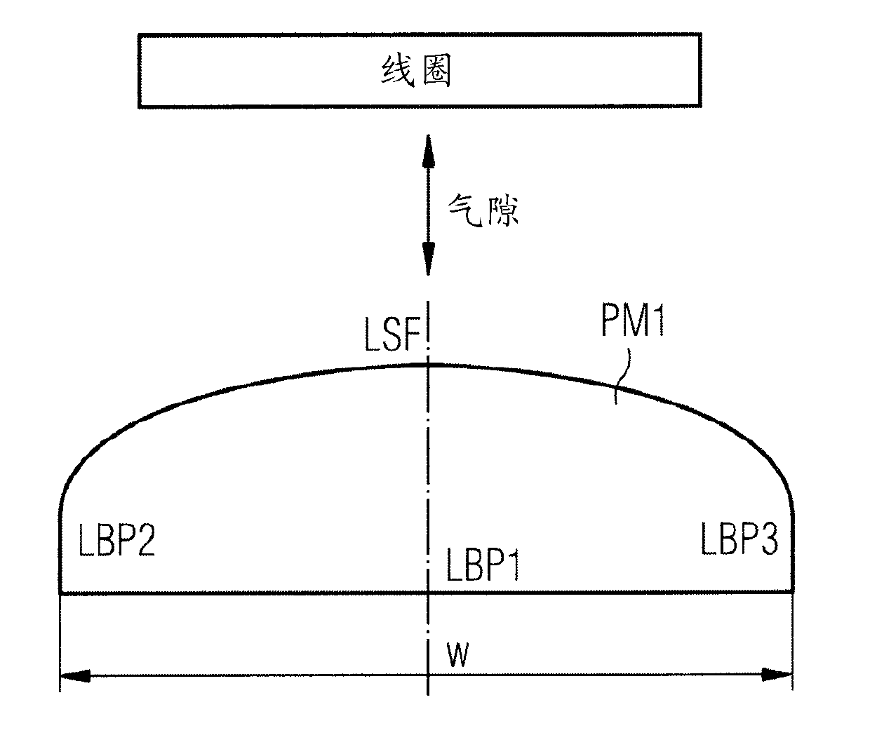
[0049] figure 1 A cross-sectional view of a permanent magnet PM1 shaped according to the present invention is shown.

[0050] The cross section of the permanent magnet PM1 includes three linear sections LBP1, LBP2, and LBP3. These sections LBP1, LBP2, LBP3 can belong to the following in figure 2 The rectangular areas shown in BP1, BP2, BP3.

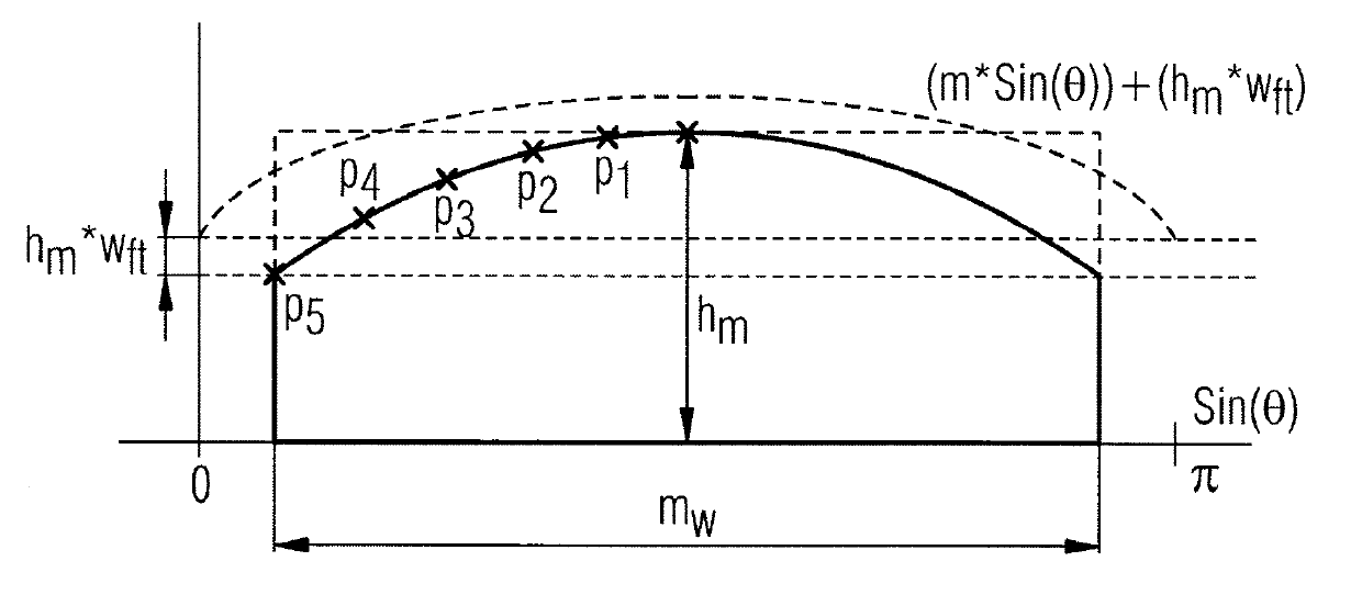
[0051] The cross section of the permanent magnet PM1 also contains the line LSF. The line LSF is shaped in such a way that it at least partially approximates a sinusoidal function. The line LSF preferably approximates the function also defined above:

[0052] .

[0053] The surface line LSF belongs to the following in figure 2 The shaped surface SF of the permanent magnet PM1 shown in .

[0054] The shaped surface ( figure 2 : SF) is aligned with the coil and with the air gap located between the permanent magnet PM1 and this coil.

[0055] figure 2 show also refer to figure 1 Perspective view of the permanent magnet PM1. ...


PUM


Abstract

The invention relates to an electrical machine, which contains permanent magnets and to the permanent magnets being used. The invention especially relates to a synchronous machine. The magnet and the coil interact with the permanent magnet via an air gap, which is located between the permanent magnet and the coil. The permanent magnet and the coil are arranged in a way that electrical power is generated in the coil when the permanent magnet or the coil is moved in their relative position to each other. The permanent magnet contains a surface, which is aligned to the coil and to the air gap in a way, that magnetic forces of the permanent magnet interact via the surface and the air gap with the coil by a magnetic flux density distribution. The cross sectional shape of this surface approximates at least partly to a sinusoidal-function.

Description

technical field [0001] The present invention relates to an electrical machine comprising permanent magnets and to the permanent magnets used. In particular, the present invention relates to a synchronizing machine. Background technique [0002] Electric machines, such as generators, contain many permanent magnets that interact with at least one coil to generate electricity. A compromise needs to be found for the magnets used. At least some of the following problems need to be minimized or even avoided: [0003] First, the magnetic force (magnetic field strength) of these magnets varies due to their individual characteristics and tolerances. If the motor is in a "no load", "idle" or "full load" state, a cyclic torque ripple occurs. [0004] Second, the number and / or size of permanent magnets used needs to be minimized due to ever increasing costs. [0005] If the motor is in an "unloaded" state, the above torque is referred to as "cogging torque", while if the motor is i...

Claims


Application Information

Patent Timeline
Patent Type & Authority Applications(China)
IPC IPC(8): H02K21/00H02K1/27
CPCH02K29/03H02K2213/03Y02E10/72H02K1/2781
Inventor A.托马斯
Owner SIEMENS GAMESA RENEWABLE ENERGY AS
Why Eureka
Try Eureka