Dispersion Compensation Method and Device

A technology of dispersion compensation and dispersion value, which is applied in the field of communication, can solve problems such as the inability to roughly adjust TDC dispersion, and achieve the effect of rough adjustment and demultiplexing

Inactive Publication Date: 2017-10-10
ZTE CORP
View PDF7 Cites 0 Cited by
  • Summary
  • Abstract
  • Description
  • Claims
  • Application Information

AI Technical Summary

Problems solved by technology

[0005] The main purpose of the present invention is to provide a dispersion compensation method and device to at least solve the above-mentioned problem that the service board based on the polarization tracking technology in the current optical transmission network cannot realize the rough adjustment of TDC dispersion by using the contrast ratio of the peak signal of the balanced receiver

Method used


Image

  • Dispersion Compensation Method and Device
  • Dispersion Compensation Method and Device
  • Dispersion Compensation Method and Device

Examples


Embodiment 1

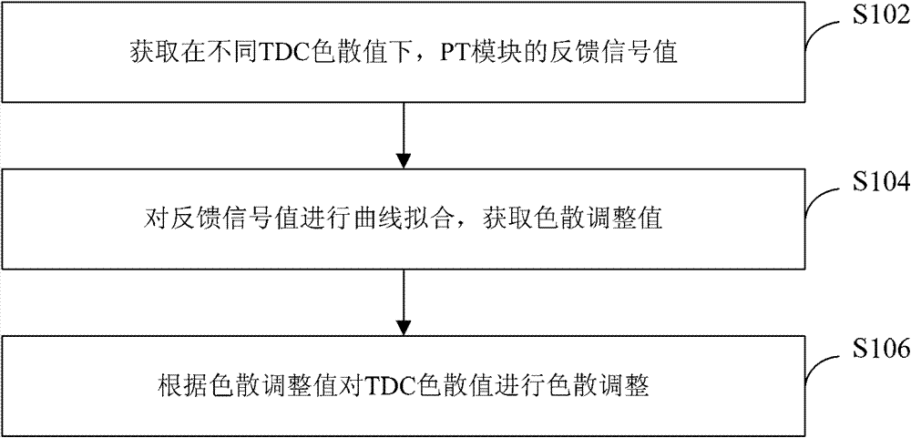
[0031] refer to figure 1 , shows a flow chart of steps of a dispersion compensation method according to Embodiment 1 of the present invention.

[0032] The dispersion compensation method of this embodiment includes the following steps:

[0033] Step S102: Obtain the feedback signal value of the PT module under different TDC dispersion values;

[0034] Within the entire threshold, during the adjustment process of the TDC dispersion value, each adjustment point collects a feedback signal value of a PT module, so as to realize the acquisition of the feedback signal value of the PT module under different TDC dispersion values.

[0035] Step S104: Perform curve fitting on the feedback signal value to obtain the dispersion adjustment value;

[0036] Curve fitting is performed on the obtained feedback signal value to obtain an optimal dispersion adjustment value.

[0037] Step S106: Perform dispersion adjustment on the TDC dispersion value according to the dispersion adjustment va...

Embodiment 2

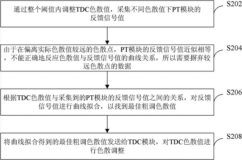
[0041] refer to figure 2 , shows a flowchart of steps of a dispersion compensation method according to Embodiment 2 of the present invention.

[0042] The dispersion compensation method of this embodiment includes the following steps:

[0043] Step S202: Collect feedback signal values ​​of the PT module under different dispersion values ​​by adjusting the TDC dispersion value within the entire threshold.

[0044] In general, the entire threshold indicates a threshold range in which the dispersion adjustment range is -700 ps / nm to 700 ps / nm, where ps / nm represents picoseconds / nanometer. But not limited thereto, those skilled in the art should understand that this embodiment is also applicable to other dispersion adjustment ranges.

[0045] Step S204: Since the feedback signal values ​​of the PT module are approximately equal at dispersion points that are far away from the actual dispersion value, the curve relationship between the dispersion value and the feedback signal value...

Embodiment 3

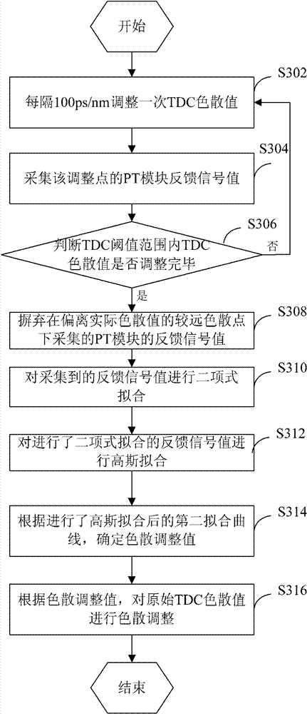
[0053] refer to image 3 , shows a flow chart of the steps of rough TDC adjustment based on PT control according to Embodiment 3 of the present invention.

[0054] The rough adjustment of TDC based on PT control in this embodiment includes the following steps:

[0055] Step S302: Adjust the TDC dispersion value every 100 ps / nm.

[0056] Step S304: Collect the PT module feedback signal value of the adjustment point.

[0057] Step S306: Determine whether the TDC dispersion value is adjusted within the TDC threshold range, if yes, execute step S308; if not, return to step S302 to continue execution.

[0058] Step S308: Discard the feedback signal value of the PT module collected at a dispersion point farther away from the actual dispersion value.

[0059] Among them, the farther dispersion point refers to the dispersion point that deviates from the set distance of the actual dispersion value. For example, take the dispersion point with the minimum value of the TDC dispersion v...


PUM


Abstract

The invention discloses a dispersion compensation method and device, wherein the dispersion compensation method includes: obtaining the feedback signal value of the PT module under different TDC dispersion values; performing curve fitting on the feedback signal value to obtain the dispersion adjustment value; according to the dispersion The adjustment value performs dispersion adjustment on the TDC dispersion value. The present invention solves the problem that the service single board based on the polarization tracking technology in the current optical transmission network cannot use the peak signal contrast of the balanced receiver to realize the rough adjustment of the TDC dispersion, and then achieves the demultiplexing of polarized light, even in the PT When the module does not demultiplex the polarization optics, it can also effectively achieve the effect of rough adjustment of the TDC.

Description

technical field [0001] The present invention relates to the communication field, in particular to a dispersion compensation method and device. Background technique [0002] During WDM long-distance transmission, due to various factors such as the environment, optical fiber, and equipment, the system produces dispersion effects. Although each transmission site will use part of the dispersion compensation technology to improve, but the overall compensation is not accurate. However, optical channel equipment for high-speed transmission, such as single-wavelength 40G or 100G equipment, cannot work without special dispersion compensation equipment, so equipment with dispersion compensation functions is essential. [0003] Under the existing DQPSK (Differential Quadrature Phase Shift Keying, differential quadrature phase shift keying, differential quadrature phase shift keying) modulation, the dispersion compensation technology mainly uses the contrast ratio of the peak signal of...

Claims


Application Information

Patent Timeline
Patent Type & Authority Patents(China)
IPC IPC(8): H04B10/61H04B10/2525
Inventor 张厚元沈百林张浩泰
Owner ZTE CORP
Why Eureka
Try Eureka