
Digital switching matrix supporting synchronic switching and synchronic switching method of digital image

A digital switching and synchronous switching technology, applied in the video field, can solve problems such as image delay and image instability, achieve the effects of prolonging life, avoiding visual impact, and ensuring synchronous switching of images

Active Publication Date: 2011-10-19
ENC DATA SERVICE CO LTD
View PDF6 Cites 10 Cited by
  • Summary
  • Abstract
  • Description
  • Claims
  • Application Information

AI Technical Summary

Problems solved by technology

[0005] The purpose of the embodiments of the present invention is to provide a high-bandwidth digital switching matrix and a synchronous switching method for digital images that support synchronous switching in order to solve the problem of image delay caused by the image switching process. time, image instability, etc., and provides a synchronization method based on the above digital switching matrix that supports synchronous switching. In practical applications, the digital switching matrix can support different synchronization modes according to different application environments

Method used


Image

  • Digital switching matrix supporting synchronic switching and synchronic switching method of digital image
  • Digital switching matrix supporting synchronic switching and synchronic switching method of digital image
  • Digital switching matrix supporting synchronic switching and synchronic switching method of digital image

Examples


Embodiment Construction

[0036] The present invention will be described in further detail below in conjunction with the accompanying drawings.

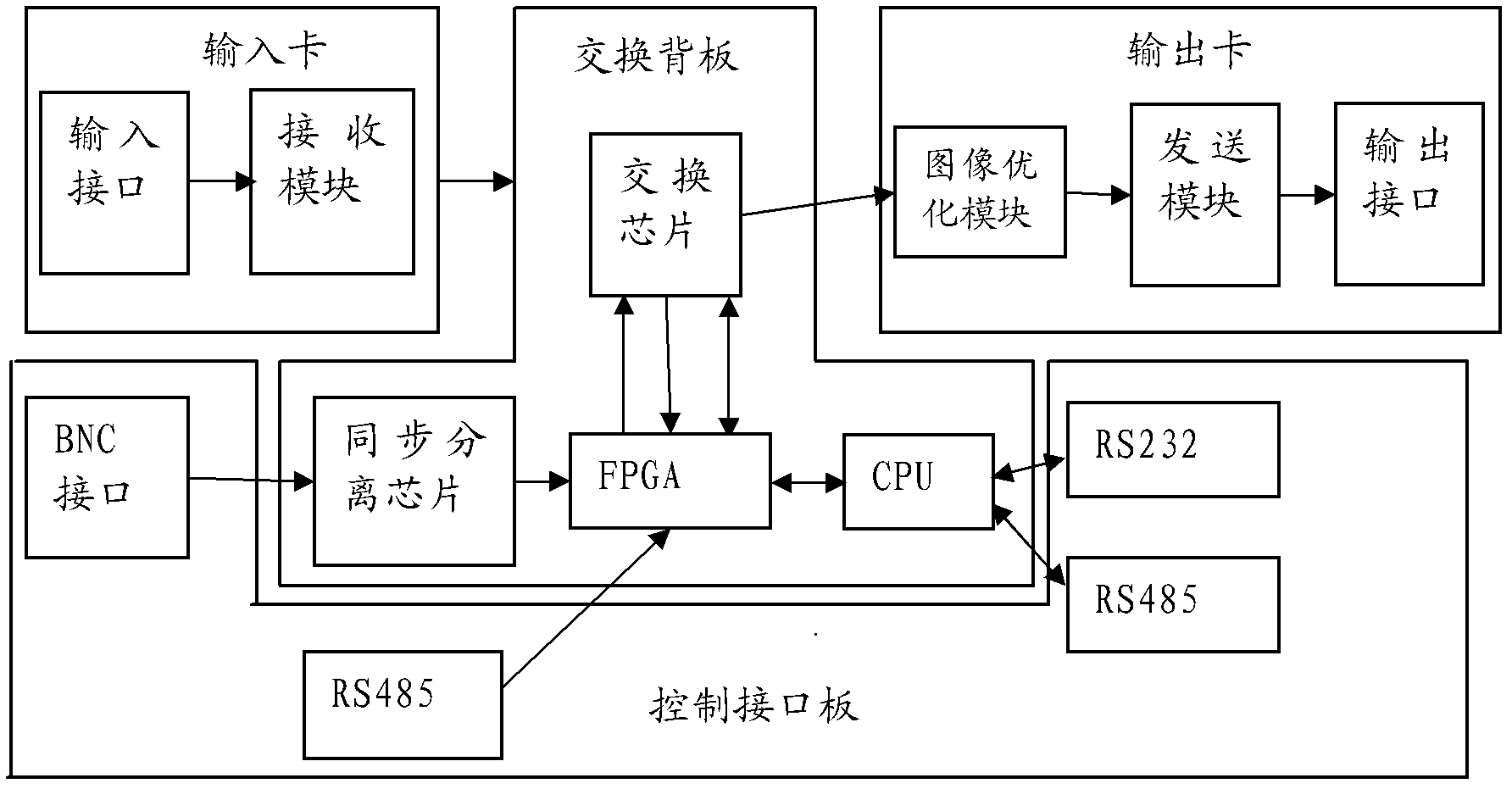
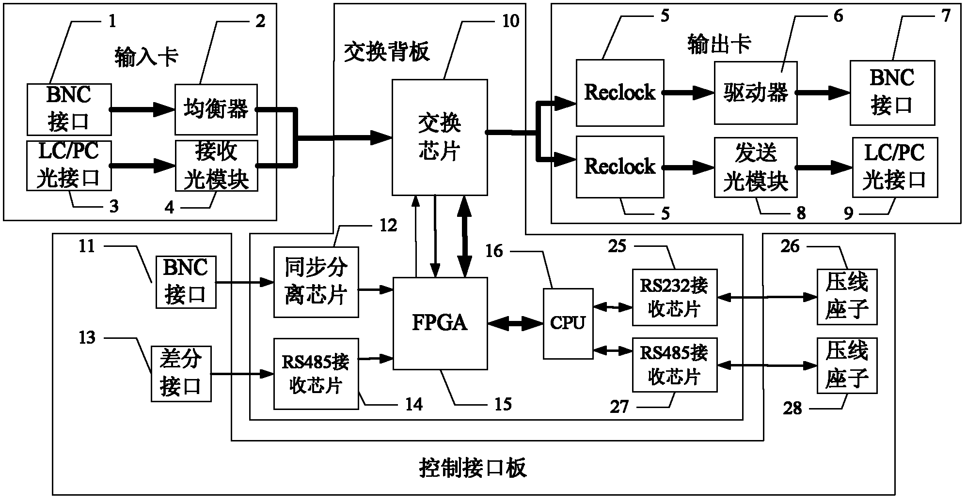
[0037] Such as figure 1 Shown is a system structure diagram of a digital switching matrix supporting synchronous switching in Embodiment 1 of the present invention. The digital switching matrix supporting synchronous switching can adopt a plug-in design to flexibly configure different interface types and switching capacities.

[0038] Specifically include:

[0039] A digital switching matrix that supports synchronous switching, the digital switching matrix includes: an input card, an output card, a switching backplane, and a control interface board, wherein,

[0040] The input card includes a receiving module and an input interface, the input end of the receiving module is connected to the input interface, and the output end is connected to the input end of the switching chip of the switching backplane;

[0041] The output card includes an image optimizatio...


PUM


Abstract

The invention discloses a digital switching matrix supporting synchronic switching, which comprises an input card, an output card, a switching backplate and a control interface plate, wherein the input card comprises a receiving module and an input interface, the input of the receiving module is connected with the input interface, and the output end of the receiving module is connected with the input of the switching chip of the switching backplate; the output card comprises an image optimization module, a transmission module and an output interface; the input of the transmission module is connected with the output end of the image optimization module, and the output end of the transmission module is connected with the output interface; the switching backplate comprises the switching chip, a CPU (Central Processing Unit) chip, an FPGA (Field Programmable Fata Array) chip and a synchronic separation chip, the output end of the switching chip is connected with the input end of the imageoptimization module, and is also connected to the serdes interface of an FPGA, the output of the synchronic separation chip is connected with the FPGA; and the control interface plate comprises an RS485 synchronic signal receiving chip, an external BNC (Bayonet Nut Connector) interface and an RS232 and / or RS485 receiving chip. By the invention, the problem that during the video image switching process, the transmission is delayed and the images are not stable can be solved, and the visual impact to a user during the image switching process can be avoided.

Description

technical field [0001] The invention relates to the field of video technology, in particular to a digital switching matrix supporting synchronous switching and a method for synchronous switching of digital images. Background technique [0002] At present, the core switching chips used in the image switching matrix on the market include FPGA, Crosspoint Switch chip and other solutions. Among them, the FPGA solution needs to perform serial-to-parallel conversion and encoding and decoding of video data, which will cause delays in video transmission. [0003] At the same time, most of the current switching methods of video images are to directly complete the switching operation according to the switching command. In this way, the image may appear in an unstable state during the switching process, and even a short black screen may appear, which will bring visual problems. The impact will affect the viewing effect. [0004] In addition, the few switch matrix products on the marke...

Claims


Application Information

Patent Timeline
Patent Type & Authority Applications(China)
IPC IPC(8): H04N5/268H04N5/08
Inventor 樊林元梁龙飞田广
Owner ENC DATA SERVICE CO LTD
Learn More