
Microphone control device and method

A control device and control method technology, applied in the direction of electrical components, etc., can solve problems such as difficult control, affect speech emotions and performance quality, delay in activity time, etc., and achieve the effect of precise activity process and time, and control of activity process and time

Inactive Publication Date: 2011-10-19
HONG FU JIN PRECISION IND (SHENZHEN) CO LTD +1
View PDF3 Cites 32 Cited by
  • Summary
  • Abstract
  • Description
  • Claims
  • Application Information

AI Technical Summary

Problems solved by technology

[0004] According to the above, different types of microphones have different ways of receiving sound, but because traditional microphones do not incorporate image detection technology, they cannot automatically detect the user's face and mouth position, and adjust to the best sound reception according to the user's height The position and angle, the user can only manually adjust the height and angle of the microphone before use
However, there will always be multiple speakers or performers in most events. Even if a professional sound engineer has been hired to set up the microphone position before the event, it is often caused by the different heights of each speaker or performer. The radio effect is different
If each speaker re-adjusts the height and angle of the microphone before giving a speech, it will not only affect the mood of the speech and the quality of the performance, but also may cause delays in the activity time and make it difficult to control. In addition, the sound collection and amplification effects of the microphones adjusted by the user themselves will also be affected. not able to achieve the best results

Method used


Image

  • Microphone control device and method
  • Microphone control device and method
  • Microphone control device and method

Examples


Embodiment Construction

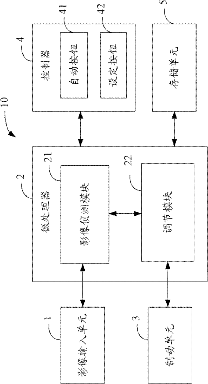
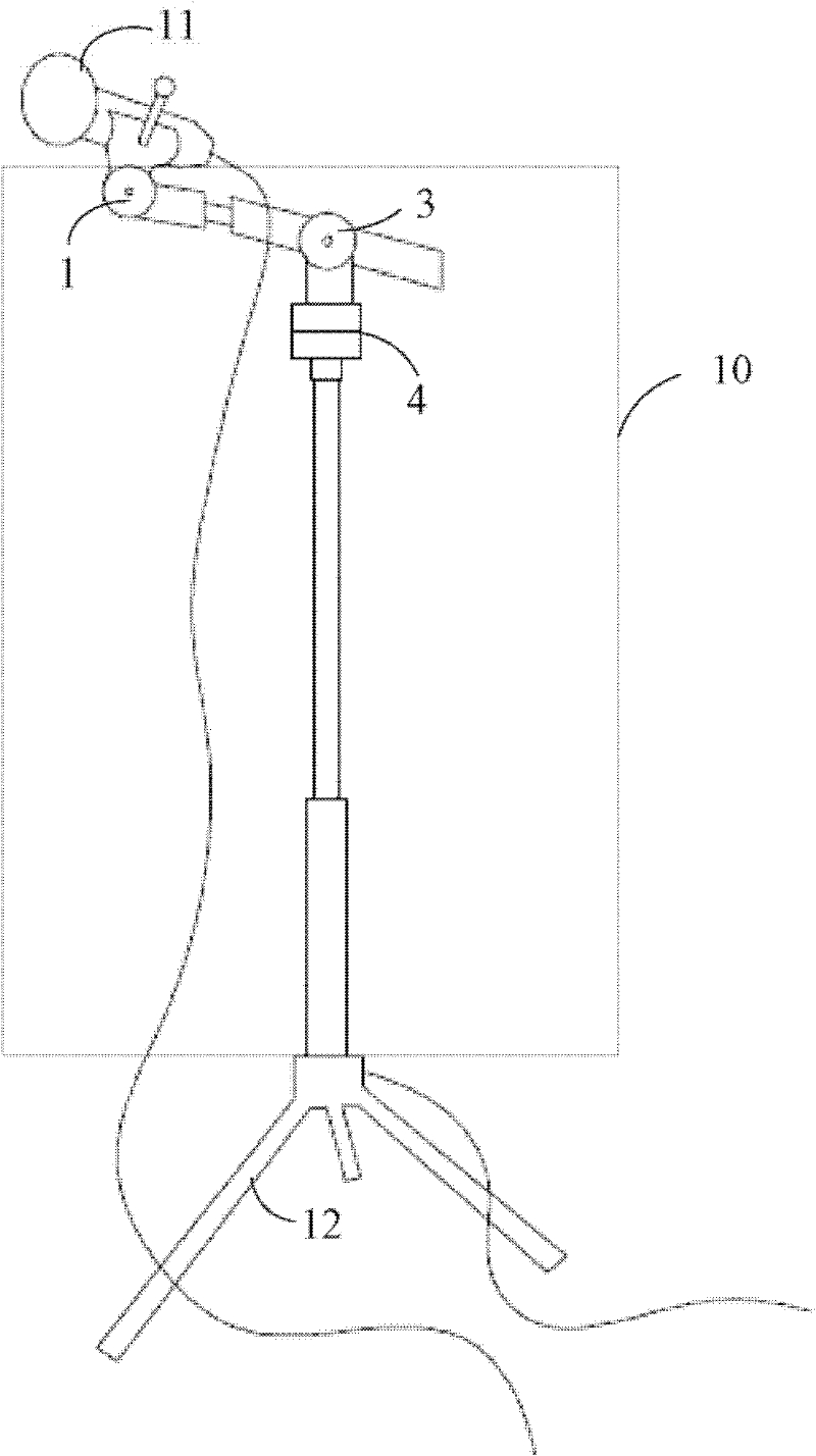
[0027] Such as figure 1 Shown is a structural diagram of a preferred embodiment of the microphone control device 10 of the present invention. The microphone control device 10 is used to automatically adjust the height, distance and angle of the microphone 11 according to the position of the user's face and mouth. refer to figure 2 As shown, the microphone 11 is mounted on a microphone control device 10 , and the microphone control device 10 is mounted on a bracket 12 . In this embodiment, the microphone control device 10 at least includes an image input unit 1 , a microprocessor 2 , a braking unit 3 , a controller 4 and a storage unit 5 .

[0028] Described image input unit 1 is connected with microprocessor 2, and it is used for photographing the scene image near microphone 11 in real time, for example Figure 4 shown in image A and Figure 5 The image B is shown, and the scene image is sent to the microprocessor 2 for image detection. In this embodiment, the image inpu...


PUM


Abstract

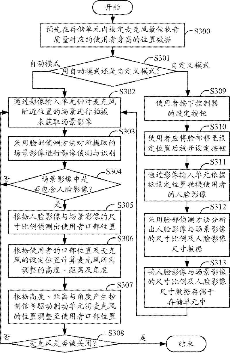
The invention discloses a microphone control device and method. The microphone control device comprises an image inputting unit, a brake unit and a microprocessor. The microprocessor comprises an image detecting module and an adjusting module; the image detecting module is used for receiving scene images shot by the image inputting unit, detecting and distinguishing the scene images by adopting a face detection method, judging whether the face image of the user is included in the scene image, and detecting the mouth position of the user according to the dimensional proportion of the face image and the scene image; and the adjusting module is used for computing the height, distance and angle of the microphone to be adjusted according to the mouth position of the user and the preset position of the microphone, and generating a control signal according to the computed height, distance and angle so as to drive the brake unit to adjust the microphone to the mouth position of the user. By use of the invention, the microphone can extract the clearest voice of the user without being manually adjusted by the user so that the microphone can achieve the best voice reception effect in real time.

Description

technical field [0001] The invention relates to a microphone and a control method thereof, in particular to a device and a method for controlling the best sound collection position of the microphone. Background technique [0002] A microphone is an energy converter that converts sound into electronic signals. Its basic principle is that when the sound diaphragm of the microphone is vibrated by sound, it converts the sound vibration into an electronic signal. The electronic signal is amplified by an amplifier and then sent to the speaker. become the original voice. Common microphones for this signal conversion method include dynamic microphones (also known as dynamic microphones) and condenser microphones. Among them, the condenser microphone is more expensive, but the sound quality is better and thinner, and the disadvantage is that it is not resistant to high voltage. [0003] In addition to the way they convert signals, microphones can also be differentiated by the way t...

Claims


Application Information

Patent Timeline
Patent Type & Authority Applications(China)
IPC IPC(8): H04R29/00
Inventor 李后贤李章荣罗治平
Owner HONG FU JIN PRECISION IND (SHENZHEN) CO LTD
Learn More