Imaging apparatus for imaging a heart

An imaging device, a technology of the heart, applied in the direction of instruments, applications, cardiac catheterization, etc. for radiological diagnosis, which can solve the problems of troublesome analysis, difficulty, inaccuracy, etc.

Inactive Publication Date: 2011-10-19
KONINKLIJKE PHILIPS ELECTRONICS NV
View PDF3 Cites 18 Cited by
  • Summary
  • Abstract
  • Description
  • Claims
  • Application Information

AI Technical Summary

Problems solved by technology

[0003] The disadvantage of this system is the extremely large amount of electroanatomical data which, for example, must be painstakingly analyzed and interpreted by the electrophysiologist in order to determine, for example, the optimal ablation site
This mental process is time-consuming and often difficult, and can lead to imprecise or sub-optimal conclusions, especially regarding optimal ablation sites

Method used


Image

  • Imaging apparatus for imaging a heart
  • Imaging apparatus for imaging a heart
  • Imaging apparatus for imaging a heart

Examples


Embodiment Construction

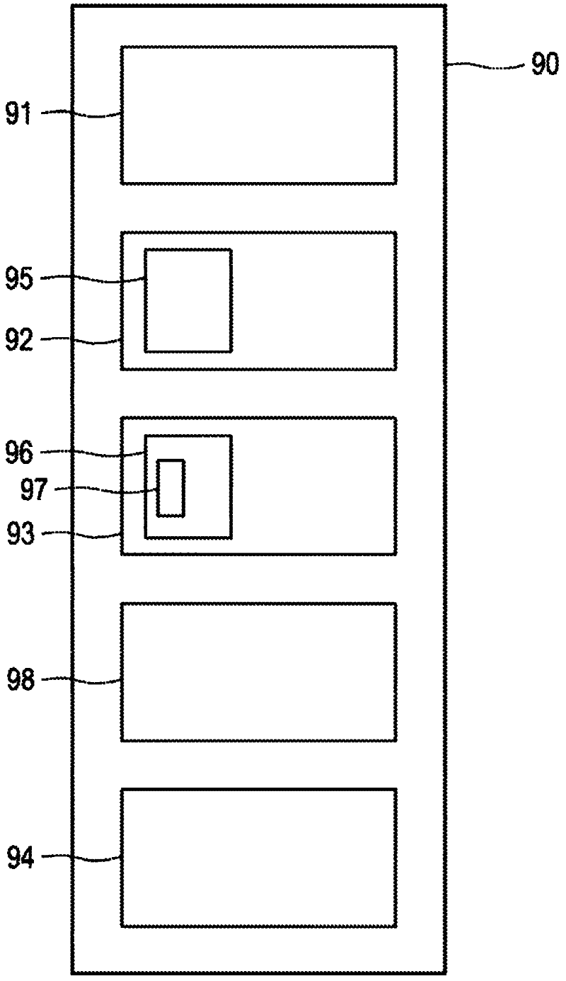
[0062] figure 1An embodiment 90 of an imaging device for imaging a heart is shown schematically and exemplarily. The imaging device includes an attribute type providing unit 91 for providing attribute types of the heart at different positions of the heart, a first portion determining unit 92 for determining a first portion of the heart, and a second portion for determining a second portion of the heart Determining unit 93, wherein the first part includes a first attribute type in the provided attribute types, and wherein the second part includes a second attribute type in the provided attribute types, and wherein the second part has the same Causality in the first part. The imaging device 90 also includes a display unit 94 for displaying the first site and the second site.

[0063] A first site and a second site are causally related if the property type of at least one of the first site and the second site causes or contributes to the property type of the other of the first...


PUM


Abstract

An imaging apparatus for imaging a heart is provided, wherein the imaging of the heart is improved such that conclusions about regions of the heart having an abnormal behaviour can be made more accurate and more optimal. The imaging apparatus comprises a first site determination unit for determining a first site of the heart comprising a first property type like a fractionated electrogram (70,71,74,75) and a second site determination unit for determining a second site comprising a second property type like a ganglionated plexus (72,73). The first site and the second site are causally related and displayed on a display unit. Since the displayed first and second sites are causally related to each other, a further information is given, i.e. the causal relation, which assists a user in finding regions of the heart showing an abnormal behaviour.

Description

technical field [0001] The invention relates to an imaging device, an imaging method and an imaging computer program for imaging the heart. Background technique [0002] The following article describes a method for determining the location of scar tissue in the heart and for electrodissection of the heart Figure 1 A system to jointly visualize these sites: "Integration of Three-Dimensional Scar Maps for Ventricular Tachycardia Ablation With Positron Emission Tomography-Computed Tomography" by T. Dickfeld et al., Journal of The American College of Cardiology Foundation, Cardiovascular Imaging, 1:73-82, 2008. [0003] A disadvantage of this system is that there is an extremely large amount of electroanatomical data which, for example, must be analyzed and interpreted by an electrophysiologist in order to determine, for example, the optimal ablation site. This mental process is time-consuming and often difficult, and can lead to imprecise or sub-optimal conclusions, especiall...

Claims


Application Information

Patent Timeline
Patent Type & Authority Applications(China)
IPC IPC(8): A61B5/042A61B5/296
CPCA61B5/02007A61B5/055A61B5/06A61B6/12A61B6/503A61B8/0833A61B8/0883A61B18/1492A61B18/20A61B2018/00577A61B2018/00702A61B2018/00791A61B2018/00839A61B5/287
Inventor M·E·巴利J·卡勒特
Owner KONINKLIJKE PHILIPS ELECTRONICS NV
Why Eureka
Try Eureka