Supercharge Your Innovation With Domain-Expert AI Agents!

Temperature-control punching machine

A punching machine and punching technology, applied in the direction of metal processing, etc., can solve the problems of heating punches, profile fragmentation, processing and feeding troubles, etc., and achieve the effects of improving work efficiency, reducing fragmentation, and reducing costs

Inactive Publication Date: 2011-11-02
大连冶金工具厂有限公司
View PDF0 Cites 12 Cited by
  • Summary
  • Abstract
  • Description
  • Claims
  • Application Information

AI Technical Summary

Problems solved by technology

The original punching machine has a large force when punching the profile, which is easy to cause the profile to break. There is a process to heat the punch and then punch the hole, which can reduce the breakage of the workpiece during punching, but heating the punch is more troublesome.
And it is more troublesome when punching and loading large workpieces

Method used


Image

  • Temperature-control punching machine
  • Temperature-control punching machine
  • Temperature-control punching machine

Examples


Embodiment Construction

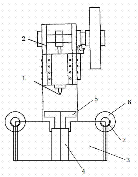
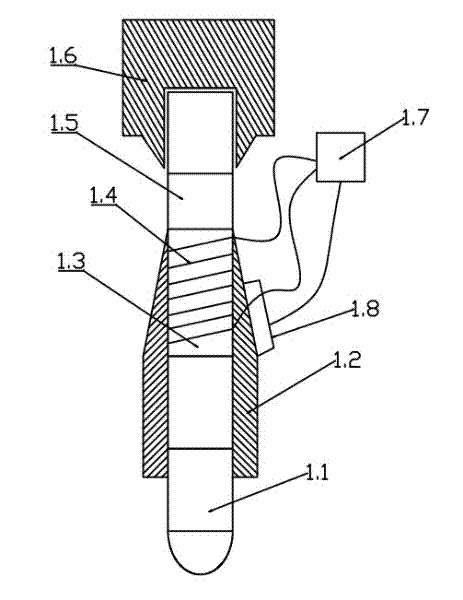
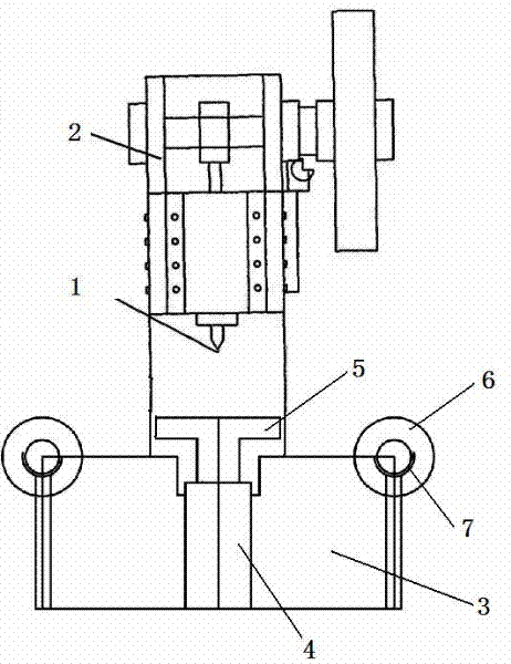
[0009] figure 1 , figure 2 The schematic diagram of a temperature-controlled punching machine shown includes a punching mechanism 1, a workbench 2, and a base 3. The punching machine is provided with a feeding mechanism 4 that drives the object to be punched to move, and is located on the base. The feeding mechanism 4 There are columns 7 at both ends, with grooves that can support the roller 6, on which the roller 6 can be passively rolled, driving the workpiece to move under the workbench 2, and the middle part is equipped with a hydraulic jacking device 5 to jack up the workpiece, The workpiece leaves the roller and is punched. The front end of the punching mechanism 1 is connected to the chain rod, the lower end of the chain rod is connected to the punch shaft 1.6, the lower port of the punch shaft 1.6 is equipped with a punch cover 1.5, the middle part of the head cover 1.5 is wound with a heat conducting rod 1.3 and the electric furnace wire 1.4, and the positive and ne...


PUM


Abstract

The invention relates to a temperature-control punching machine, belonging to the field of machining equipment. The temperature-control punching machine is provided with a feeding mechanism for driving an object to be punched to move; the feeding mechanism is located on a base; the two ends of the feeding mechanism are provided with upright posts which are provided with concave grooves capable of supporting rolling shafts; the rolling shafts mounted on the upright posts can be driven to roll, so that a workpiece is driven to move to a position below a worktable; the middle part of the worktable is provided with hydraulic jack devices for jacking the workpiece; and when the workpiece leaves the rolling shafts, punching is carried out. The front end of the punching machine is connected with a chained rod; the lower end of the chained rod is connected to a punch shaft; a lower opening of the punching head shaft is provided with a punching head sleeve; an electric furnace heating wire is wound on a heat-conducting rod at a middle part of the punching head sleeve; the positive pole and the negative pole of the punching head sleeve are connected with a temperature-control device; the lower end of the punch sleeve is provided with a chuck which clamps a punching head; and a temperature sensor is adhered to the outside of the lower end of the punching head sleeve and is connected to the temperature-control device. With the adoption of the temperature-control punching machine, the temperature of the punching head is constant during the punching action, so that the fragmenting rate of workpieces is reduced, and the cost is lowered. As the punching machine is provided with the feeding mechanism for driving the object to be punched to move, and when the punching machine works, the feeding mechanism can automatically feed materials, thus the working efficiency can be greatly enhanced.

Description

technical field [0001] The invention relates to mechanical processing equipment, in particular to a temperature-controlled punching machine. Background technique [0002] Drilling is the process of using a drill bit to drill a hole in the processed material, while punching is the process of punching the drill bit down to form a hole due to gravity. Drilling machines are suitable for processing hard materials, because the punching force of the punching machine tends to cause cracks in the processed material. The original punching machine has a large force when punching the profile, which is easy to cause the profile to break. There is a process to heat the punch and then punch the hole, which can reduce the breakage of the workpiece during punching, but heating the punch is more troublesome. . And the punching processing of large workpieces is also troublesome. Contents of the invention [0003] In view of the defects in the prior art, the main purpose of the technical s...

Claims


Application Information

Patent Timeline
IPC IPC(8): B26F1/02
Inventor 原春光
Owner 大连冶金工具厂有限公司
Features
  • R&D
  • Intellectual Property
  • Life Sciences
  • Materials
  • Tech Scout
  • Unparalleled Data Quality
  • Higher Quality Content
  • 60% Fewer Hallucinations
Learn More