Vehicle mechanical energy-saving hydraulic system with multi-pump confluence

A hydraulic system and vehicle technology, applied to mechanical equipment, vehicle parts, fluid steering mechanisms, etc., can solve problems such as reducing labor productivity, wasting throttling losses, reducing engine drive power output, etc., to improve operational stability and reduce energy consumption. Effect of reducing flow loss and overflow loss

Inactive Publication Date: 2011-11-02
SICHUAN UNIV
View PDF9 Cites 42 Cited by
  • Summary
  • Abstract
  • Description
  • Claims
  • Application Information

AI Technical Summary

Problems solved by technology

If the set pressure of the overflow valve of the working system is low, due to the use of a quantitative working pump, when the engine is running at high speed, the output flow of the pump is high, and the excess oil overflows, resulting in overflow loss
If the setting pressure of the overflow valve of the working system is high, when the engine is running at high speed, the maximum power that the working system can absorb is relatively high, which will easily cause the engine to crash
At the same time, the large power waste caused by the overflow and throttling of the working and steering hydraulic systems reduces the driving power output of the engine to the locomotive itself, reducing labor productivity
[0004] In order to overcome the shortcomings of the above-mentioned working hydraulic system and steering hydraulic system working independently, the improved hydraulic system currently proposed is

Method used


Image

  • Vehicle mechanical energy-saving hydraulic system with multi-pump confluence
  • Vehicle mechanical energy-saving hydraulic system with multi-pump confluence
  • Vehicle mechanical energy-saving hydraulic system with multi-pump confluence

Examples


Embodiment Construction

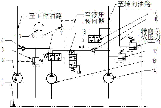
[0020] Option One( figure 1 ): When the engine speed is low, in order to ensure the required oil for the steering hydraulic system, the solenoid valve (8) is energized and opened, and part of the oil output by the pressure reducing valve (9) flows to the hydraulic steering gear, and the other part flows to the flow conversion valve The pressure control oil port overcomes the spring force of the flow switching valve (7), and when the outlet pressure of the pressure reducing valve (9) reaches a certain value, the flow switching valve (7) is in the right position, and the auxiliary pump (13) and the steering The oil output from the pump (14) merges together to supply oil to the steering hydraulic system, giving priority to steering.

[0021] When the engine speed is high, the output oil of the steering pump (14) alone has met the requirements of the steering hydraulic system; at this time, the solenoid valve (8) is powered off and closed, the flow conversion valve (7) is in the ...


PUM


Abstract

The invention relates to a vehicle mechanical energy-saving hydraulic system adopting a fixed displacement pump. The system comprises a working pump, an auxiliary pump and a steering pump; when an engine is at the lower speed, the auxiliary pump and the steering pump are converged, and the requirement of a steering system on an oil liquid is ensured; when the engine is at the high speed, the auxiliary pump and the working pump are converged, oil is provided to a working system, and the operation efficiency is improved; when the engine has high rotation speed and the working system has higher loading, and the working system requires a high-pressure small-flow-rate oil liquid, the auxiliary pump is subjected to low-pressure unloading through an equivalent unloading valve; an electromagneticvalve is introduced to the outlet of the reducing valve of the steering system, the on-off state of the electromagnetic valve is controlled by control signals which are the signals directly relevant to the engine or the engine rotation speed, and further the working position of a flow changeover valve is controlled, thus the flow direction of the oil liquid output by the auxiliary pump is controlled; and through the hydraulic system, the hydraulic system efficiency is improved, the working is reliable, the structure is simple, and the hydraulic system is easy to implement.

Description

technical field [0001] The patent of the invention relates to an energy-saving construction machinery hydraulic system, which belongs to the field of construction machinery energy conservation. Background technique [0002] The hydraulic system of many construction machinery consists of two parts: working hydraulic system (working oil circuit), steering hydraulic system (steering oil circuit); the working system is used for work; the steering hydraulic system is used for steering. At present, due to the high cost of the variable pump system, inconvenient maintenance, and easy damage, many construction machinery in China still use quantitative pumps to form their hydraulic systems. [0003] The more common domestic hydraulic system using quantitative pumps is that the working hydraulic system and the steering hydraulic system each constitute an independent hydraulic circuit, which does not affect each other; the displacement of the steering pump of this hydraulic system must ...

Claims


Application Information

Patent Timeline
IPC IPC(8): B60R16/08B62D5/06F15B11/17
Inventor 韩嘉骅谭兆钧姚进
Owner SICHUAN UNIV
Why Eureka
Try Eureka