
Cutting blade saw and manufacturing method thereof

A blade and cutting machine technology, which is applied in the cutting tool manufacturing, tool manufacturing, application and other directions of the sawing machine device, can solve the problems of poor cutting performance, smaller area, and the blade 106 falls off, and achieves wear inhibition, good cutting performance, and inhibition of falling off. Effect

Inactive Publication Date: 2011-11-09
宫电高周波设备(上海)有限公司
View PDF7 Cites 4 Cited by
  • Summary
  • Abstract
  • Description
  • Claims
  • Application Information

AI Technical Summary

Problems solved by technology

As a result, the protruding directions of the blades 106, 107 as blades have an angle with respect to the flat portion 102a of the base metal disk 102, and cannot be substantially in the same direction as the flat portion 102a, so it is difficult for the blades to enter miscellaneous wood at right angles, thereby deteriorating its cutting performance. Difference
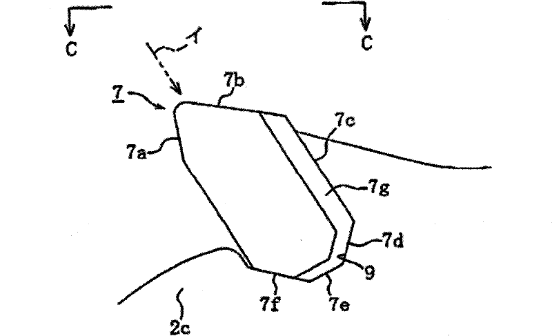
[0006] In addition, if the blades 106, 107 installed on the blade portion 102c of the base metal plate 102 by brazing on the tip blade mounting portion 105 are brazed according to the form shown in FIG. The front 106a of the blade 106 as the cutting edge, but the brazing area (mounting area) is small, and the blade 106 is prone to fall off
On the contrary, if brazing is carried out according to the form shown in Fig. 11 (b), though the brazing area can be increased to a certain extent, the area of ​​the front 107a of the blade 107 as the cutting edge is just easy to become small, in order to improve If the cutting performance is improved, the blade 107 needs to be ground again. As a result, it will be difficult to prolong the life of the blade saw 101. No matter which form of the blade saw 101 has a long and a short

Method used


Image

  • Cutting blade saw and manufacturing method thereof
  • Cutting blade saw and manufacturing method thereof
  • Cutting blade saw and manufacturing method thereof

Examples


Embodiment Construction

[0032] Embodiments for carrying out the present invention will be described in detail below based on the drawings.

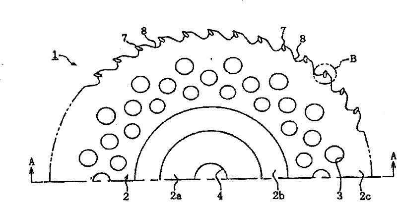
[0033] Figure 1 to Figure 7 This is an embodiment of the cutting blade saw according to the present invention. like figure 1 and figure 2 As shown, the blade saw 1 for cutting (become the blade saw 1) is provided with a disc-shaped base metal disk 2 with a plurality of lightweight holes 3 formed therein, and at the center of the base metal disk 2 is formed a 5 Mounting holes 4 for installation.

[0034] In addition, the base metal disk 2 has a flat portion 2a of a predetermined width formed on the outside of the mounting hole 4; figure 2A step portion 2b protruding in a downward oblique direction with a height h is formed on the outside of the step portion 2b, and a flat blade portion 2c is formed. Then, on the base metal disk 2, a circular space-shaped concave portion 6 viewed from the step portion 2b to its inner side is formed, and at the same time, ...


PUM


Abstract

The invention relates to a cutting blade saw and a manufacturing method thereof, which can protect a mounting bolt arranged on a cutting machine and reduce wear on the head of the bolt, smoothly replace the blade saw on the cutting machine, enlarge blade brazing area relative to a blade mounting part on the tope end of an edge part, and control reduction of cutting property. The cutting blade saw is characterized in that a matrix metal disc is equipped with a flat part, a segment difference part and the edge part, wherein, the flat part for a mounting hole arranged on the cutting machine is formed at a central part; the segment difference part is arranged outside the flat part and protrudes at the opposite side of the cutting machine; the edge part is arranged outside the segment difference part, is approximately parallel to the flat part and stretches along the direction of the top end of the edge part of the matrix metal disc; and when the flat part is arranged on the cutting machine through the mounting bolt, the height of the segment difference part is greater than protruding size of the mounting bolt. In addition, blades are characterized in that hand guards are respectively formed at two sides along the thickness direction of mounting surfaces arranged at the blade mounting part of the matrix metal disc.

Description

technical field [0001] The present invention relates to a cutting blade saw mounted on a cutting machine and used for cutting weeds and trees, and a manufacturing method thereof. Background technique [0002] Conventionally, as a blade saw for cutting, for example, Figure 10 And the blade saw shown in Figure 11 is well known. like Figure 10 As shown, the blade saw 101 has a mounting hole 103 for mounting to the cutting machine 104 on the flat portion 102a of the central portion of the disc-shaped base metal disk 102, and at the same time, a downward expansion is formed around the outer side of the flat portion 102a. The ring-shaped bulging portion 102b. In addition, on the outside of the bulging portion 102b of the base metal disk 102, the blade portion 102c faces the direction of the flat portion 102a and is tilted backward. [0003] Then, as shown in FIGS. 11( a ) and ( b ), blades 106 , 107 are respectively mounted by brazing on the blade attachment portion 105 at the...

Claims


Application Information

Patent Timeline
Patent Type & Authority Applications(China)
IPC IPC(8): B23D61/04B23D65/00A01M21/02
Inventor 宫崎力
Owner 宫电高周波设备(上海)有限公司
Learn More